
Method for uncertainty quantifiation in the performance and risk assessment of a carbon dioxide storage site

Active Publication Date: 2010-11-25
SCHLUMBERGER TECH CORP
View PDF16 Cites 53 Cited by
  • Summary
  • Abstract
  • Description
  • Claims
  • Application Information

AI Technical Summary

Benefits of technology

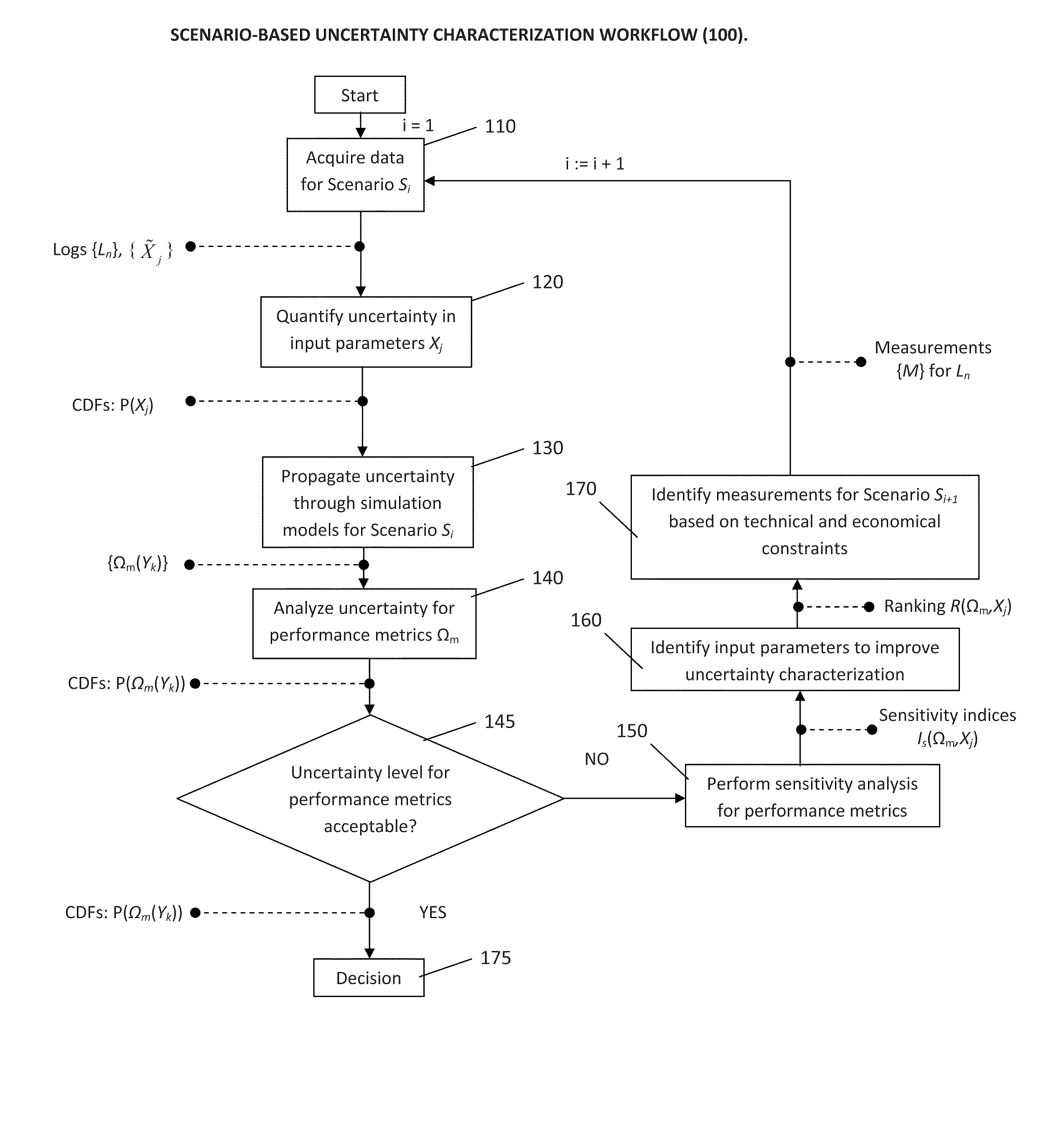
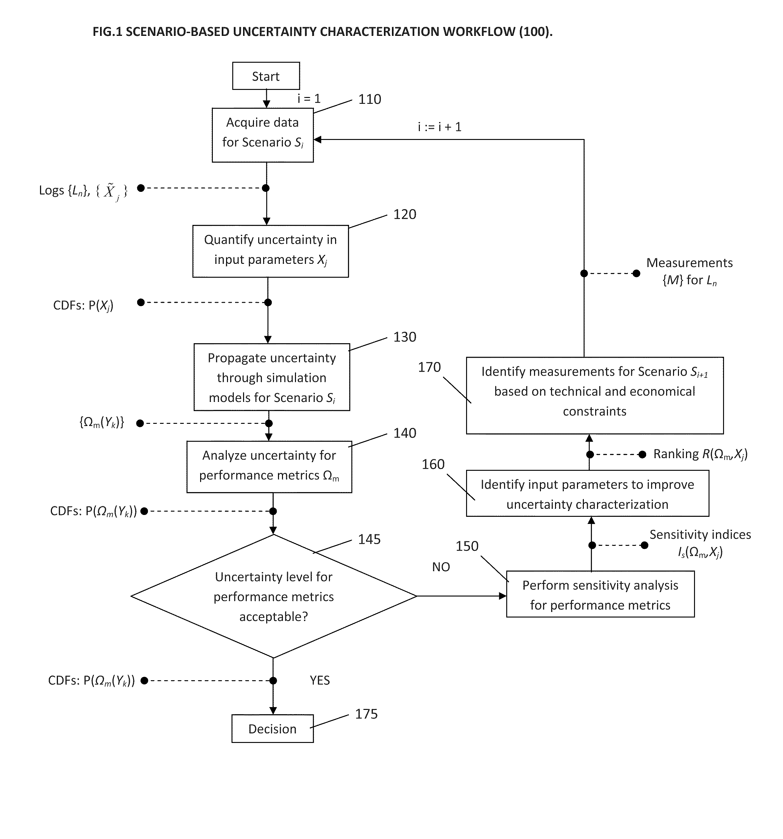
[0011]According to one embodiment of the invention, a CO2 sequestration site is evaluated by incorporating a consistent petrophysical framework having uncertainties expressed in the form of probability density functions of wellbore measurements, by systematically propagating the uncertainties to generate probability density functions or cumulative distribution functions of the parameters used in a reservoir simulation, by using reservoir simulation to thus transform the first set of p

Problems solved by technology

However, several key issues need to be resolved before large-scale geological CO2 sequestration becomes feasible.
Predictive reservoir simulations, based upon which decisions are routinely made, are rarely definitive.
More often than not, data are either sparse, or of such a low resolution and of a low information content that uncertainties in the outcomes must be estimated.
For example, failure to properly quantify the vertical movement of the CO2 plume could result in leakage into the atmosphere or into potable water supplies.
Similarly, failure to properly quantify the radial movement of the plume could result in movement into uncapped wells or into property that was not leased or acquired for sequestration.
Unfortunately, whilst single-phase flow behavior may be estimated over large numbers of samples, multiphase flow properties are time consuming to acquire and are error prone even in the laboratory.
Furthermore, procuring formation samples along a given lithology away from a wellbore is prohibitive.
Geostatistical methods are ill-suited for this purpose, because of i) unavailability of statistics away from the wellbore, and ii) impracticality of acquiring the data required to carry out predictive multiphase flow calculations.

Method used


Image

  • Method for uncertainty quantifiation in the performance and risk assessment of a carbon dioxide storage site
  • Method for uncertainty quantifiation in the performance and risk assessment of a carbon dioxide storage site
  • Method for uncertainty quantifiation in the performance and risk assessment of a carbon dioxide storage site

Examples


Embodiment Construction

[0046]The following description provides exemplary embodiments only, and is not intended to limit the scope, applicability, or configuration of the disclosure. Rather, the following description of the exemplary embodiments will provide those skilled in the art with an enabling description for implementing one or more exemplary embodiments. It being understood that various changes may be made in the function and arrangement of elements without departing from the spirit and scope of the invention as set forth in the appended claims.

[0047]Specific details are given in the following description to provide a thorough understanding of the embodiments. However, it will be understood by one of ordinary skill in the art that the embodiments may be practiced without these specific details. For example, systems, processes, and other elements in the invention may be shown as components in block diagram form in order not to obscure the embodiments in unnecessary detail. In other instances, well-...


PUM


Abstract

A CO2 sequestration site is evaluated by incorporating a consistent petrophysical framework having uncertainties expressed in the form of probability density functions of wellbore measurements, by systematically propagating the uncertainties in generating probability density functions or cumulative distribution functions of the parameters used in a reservoir simulation, by using the reservoir simulation to transform the first set of parameters into output variables with uncertainties, and by using the output variables and uncertainties to generate an answer product from which uncertainty levels of performance metrics can be ascertained.

Description

CLAIM OF PRIORITY[0001]This application claims priority from Ser. No. 61 / 173,025 filed Apr. 27, 2009, which is hereby incorporated by reference herein in its entirety.FIELD OF THE INVENTION[0002]This invention relates broadly to a method for formation parameter uncertainty propagation and quantification in the context of generating answer products relating to the storage of carbon dioxide within an underground formation. More particularly, this invention relates to a method for computing statistical measures of performance metrics related to containment, injectivity, and displacement characteristics of carbon dioxide linked to an underground formation targeted sequestration.BACKGROUND OF THE INVENTION[0003]Carbon dioxide (CO2) geological storage is one of the approaches considered for stabilizing atmospheric CO2 concentrations. Captured CO2 from a source such as coal-fired power plant flue gas is injected through a well into the subsurface, e.g. saline aquifers, where it is likely t...

Claims


Application Information

Patent Timeline
IPC IPC(8): G06G7/50
CPCG01V2210/667G01V11/00Y02P90/70Y02C20/40
Inventor CHUGUNOV, NIKITA V.STABINSKI, ERIC LEONRAMAKRISHNAN, TERIZHANDUR S.DE LOUBENS, ROMAINALTUNDAS, YUSUF BILGINESPINAL, LAURA
Owner SCHLUMBERGER TECH CORP
Learn More