Hydrocarbon gas processing

a technology of hydrocarbon gas and processing equipment, applied in the direction of liquefaction, gaseous mixture working up, lighting and heating equipment, etc., can solve the problems of not only the capital but also the operating cost of the plant, and the inability to use feed gas cooling in the heat exchanger

Inactive Publication Date: 2005-07-12
UOP LLC
View PDF38 Cites 193 Cited by
  • Summary
  • Abstract
  • Description
  • Claims
  • Application Information

AI Technical Summary

Benefits of technology

[0010]The purpose of this process is to perform a separation that produces a residue gas leaving the process which contains substantially all of the methane in the feed gas with essentially none of the C2 components and heavier hydrocarbon components, and a bottoms fraction leaving the demethanizer which contains substantially all of the C2 components and heavier hydrocarbon components with essentially no methane or more volatile components while meeting plant specifications for maximum permissible carbon dioxide content. The present invention provides a means for providing a new plant or modifying an existing processing plant to achieve this separation at significantly lower capital cost by reducing the size of or eliminating the need for a product treating system for removal of carbon dioxide. Alternatively, the present invention, whether applied in a new facility or as a modification to an existing processing plant, can be used to recover more C2 components and heavier hydrocarbon components in the bottom liquid product for a given carbon dioxide concentration in the feed gas than other processing schemes.
[0011]In accordance with the present invention, it has been found that C2 recoveries in excess of 66 percent can be maintained while maintaining the carbon dioxide content of the bottom liquid product within specifications and providing essentially complete rejection of methane to the residue gas stream. The present invention, although applicable at lower pressures and warmer temperatures, is particularly advantageous when processing feed gases at pressures in the range of 600 to 1000 psia or higher under conditions requiring column overhead temperatures of −120° F. or colder.
[0012]The present invention uses a modified reboiler scheme which can be applied to any type of NGL recovery system. In a typical reboiler or side reboiler application in a distillation column, the entire column down-flowing liquid stream is withdrawn from the tower and passed through a heat exchanger, then returned to the column at essentially the same point in the column. In this modified reboiler system, a portion of the column down-flowing liquid is withdrawn from a point higher in the column, i.e., separated from the return point by at least one theoretical stage. Even though the flow rate of the liquid may be lower, it is usually much colder and can have advantages in improving recovery or reducing exchanger size.
[0013]It has been found that when the present invention is applied to prior art processes for NGL recovery, the recovery of C2 components and heavier components is improved by one to two percent. The improvement in recovery is much greater, however, when it is desirable to reduce the carbon dioxide content in the recovered NGL product. Recovery of ethane in a typical NGL recovery plant also results in recovery of at least some of the carbon dioxide contained in the feed gas because carbon dioxide falls in between methane and ethane in relative volatility. Therefore, as ethane recovery increases, so does the recovery of carbon dioxide in the NGL product. By applying the modified reboiler scheme of the present invention, the applicants have found that it is possible to significantly improve recovery of ethane in the NGL product compared to use of the conventional reboiler or side reboiler systems when the column is reboiled to meet the desired carbon dioxide content in the NGL product.

Problems solved by technology

There are many options for removing the carbon dioxide (treating the incoming feed gas, treating the total liquid product, treating the ethane product after fractionation, etc.), but all of these options will add not only to the capital cost of the plant (due to the cost of installing the treating system) but also to the operating expense of the plant (due to energy and chemical consumption in the treating system).
Because stream 43a is so warm, however, it cannot be used for feed gas cooling in heat exchanger 10.
Unfortunately, the resulting carbon dioxide:ethane ratio (0.087:1) is too high to meet the plant owner's specification when the plant is operated in this manner.
Since the relative volatilities for carbon dioxide and ethane are very similar, the ethane vapor is a much less effective stripping agent than the methane vapor, which reduces the stripping efficiency in the column and causes lower recovery.

Method used


Image

  • Hydrocarbon gas processing
  • Hydrocarbon gas processing
  • Hydrocarbon gas processing

Examples


example

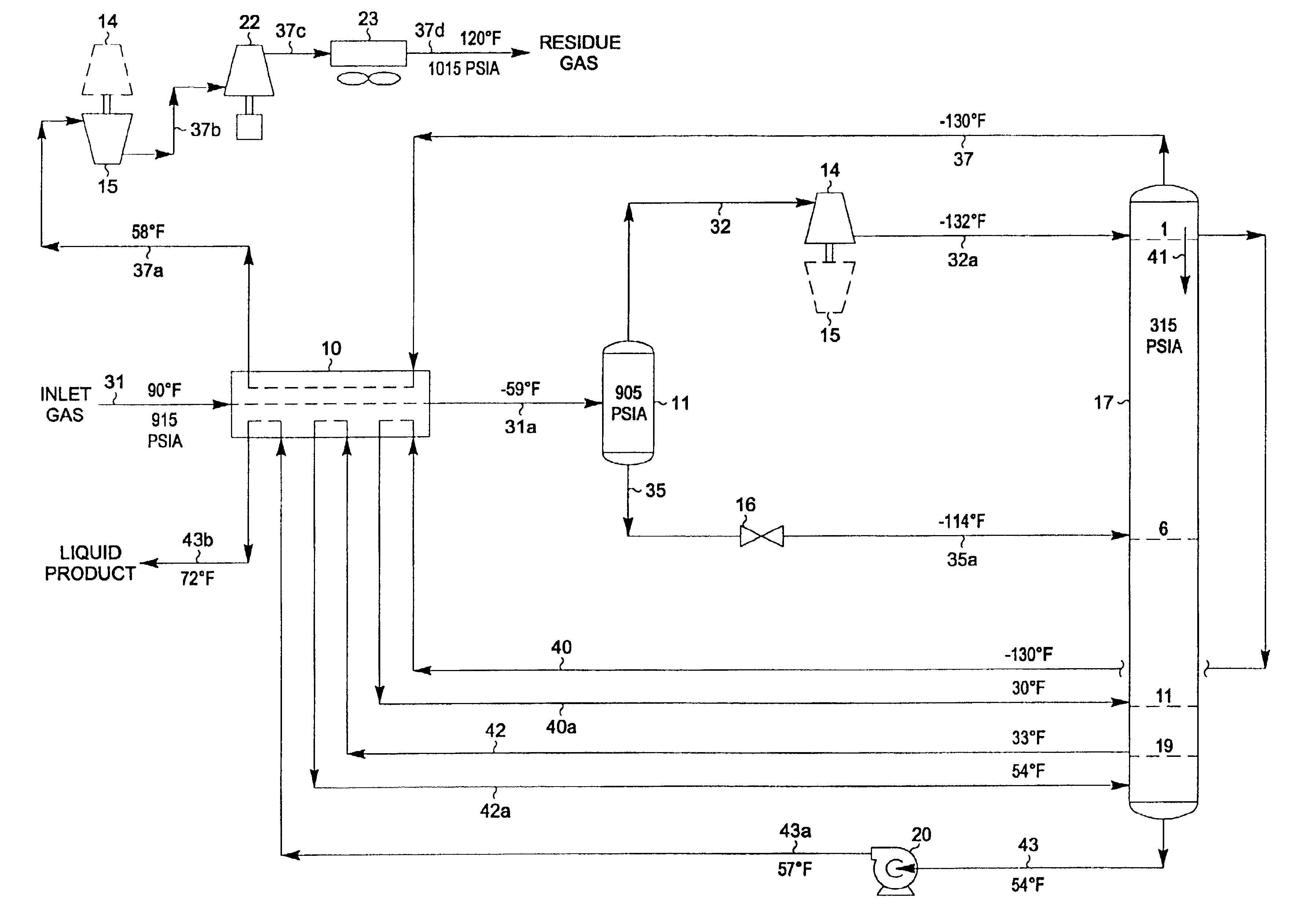
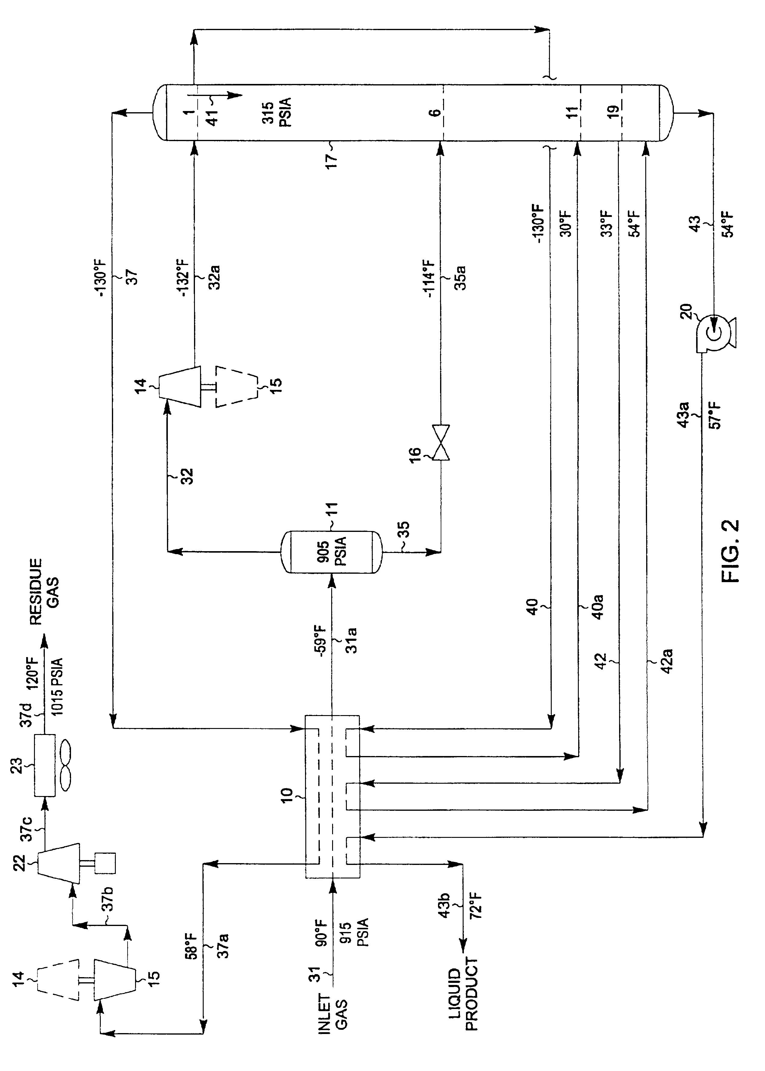
[0037]FIG. 2 illustrates a flow diagram of a process in accordance with the present invention. The feed gas composition and conditions considered in the process presented in FIG. 2 are the same as those in FIG. 1. Accordingly, the FIG. 2 process can be compared with that of the FIG. 1 process to illustrate the advantages of the present invention.

[0038]In the simulation of the FIG. 2 process, inlet gas enters at 90° F. and a pressure of 915 psia as stream 31. The feed stream 31 is cooled in exchanger 10 by heat exchange with cold residue gas at −130° F. (stream 37), demethanizer liquid product at 57° F. (stream 43a), demethanizer reboiler liquids at 33° F. (stream 42), and a portion of the liquids from the upper section of demethanizer column 17 at −130° F. (stream 40). The cooled stream 31a enters separator 11 at −59° F. and 905 psia where the vapor (stream 32) is separated from the condensed liquid (stream 35).

[0039]The condensed liquid (stream 35) from separator 11 is flash expand...


PUM

PropertyMeasurementUnit
mole percentaaaaaaaaaa

Abstract

A process for the recovery of ethane, ethylene, propane, propylene and heavier hydrocarbon components from a hydrocarbon gas stream is disclosed. In recent years, the preferred method of separating a hydrocarbon gas stream generally includes supplying at least portions of the gas stream to a fractionation tower having at least one reboiler, and often one or more side reboilers, to supply heat to the column by withdrawing and heating some of the tower liquids to produce stripping vapors that separate the more volatile components from the desired components. The reboiler and side reboilers (if any) are typically integrated into the feed stream cooling scheme to provide at least a portion of the refrigeration needed to condense the desired components for subsequent fractionation in the distillation column. In the process disclosed, the tower reboiling scheme is modified to use one or more tower liquid distillation streams from a point higher in the column than is used in the conventional reboiling scheme, providing colder stream(s) for the reboiler(s) that allow more effective cooling of the feed streams and thereby improve the efficiency with which the desired components are recovered. In addition, the tower liquid streams withdrawn from a higher point in the column contain larger quantities of the more volatile components, which when vaporized provide better stripping of undesirable components like carbon dioxide without reducing the recovery of the desired components. The heated distillation stream is returned to a lower point on the fractionation tower that is separated from the withdrawal point by at least one theoretical stage.

Description

CROSS REFERENCE TO RELATED APPLICATIONS[0001]This application is a continuation application under 37 C. F. R. 1.53(b) of application Ser. No. 09 / 677,220 filed Oct. 2, 2000.BACKGROUND OF THE INVENTION[0002]This invention relates to a process for the separation of a gas containing hydrocarbons.[0003]Ethylene, ethane, propylene, propane and / or heavier hydrocarbons can be recovered from a variety of gases, such as natural gas, refinery gas, and synthetic gas streams obtained from other hydrocarbon materials such as coal, crude oil, naphtha, oil shale, tar sands, and lignite. Natural gas usually has a major proportion of methane and ethane, i.e., methane and ethane together comprise at least 50 mole percent of the gas. The gas also contains relatively lesser amounts of heavier hydrocarbons such as propane, butanes, pentanes and the like, as well as hydrogen, nitrogen, carbon dioxide and other gases.[0004]The present invention is generally concerned with the recovery of ethylene, ethane, ...

Claims


Application Information

Patent Timeline
Patent Type & Authority Patents(United States)
IPC IPC(8): C07C7/00C10G70/00C10G70/04C10G5/06C10G5/00F25J3/02
CPCC07C7/005C10G5/06C10G70/04F25J3/0209F25J3/0219F25J3/0233F25J3/0238F25J2200/02F25J2200/70F25J2200/74F25J2200/90F25J2205/04F25J2210/12F25J2220/66F25J2235/60F25J2240/02F25J2245/02F25J2270/02F25J2290/40Y02C10/12Y02C20/40
Inventor WILKINSON, JOHN D.HUDSON, HANK M.PIERCE, MICHAEL C.
Owner UOP LLC
Why Eureka
Try Eureka