Marine pipeline heated with alternating current

a technology of alternating current and pipeline, which is applied in the direction of electrochemical variables of materials, instruments, boreholes/wells, etc., can solve the problems of preventing the use of concentric pipes with insulation-filled annulus, more conductive, and high cost for a given volum

Inactive Publication Date: 2000-04-11
SUMNER GLEN R
View PDF16 Cites 56 Cited by
  • Summary
  • Abstract
  • Description
  • Claims
  • Application Information

AI Technical Summary

Problems solved by technology

Reeling, however, generally precludes the use of a concentric pipe with an insulation-filled annulus except on very small flow lines, due to the stiffness of the composite pipe.
Various plastic, rubber or foamed plastic coatings have been used to insulate reel laid pipes, but these are both more expensive for a given volume, and more conductive than conventional insulating materials that can be used in a concentric pipe design.
Because several flow lines are often laid along the same short route, it is sometimes less expensive to assemble the flow lines onshore and tow a bundle of several pipelines to the offshore site, particularly if insulation is needed.
One disadvantage of housing the bundled lines inside a casing pipe is that in very deep water the wall thickness required to keep the casing pipe from collapsing under the hydrostatic pressure makes it difficult to achieve the desired buoyancy.
This has been overcome in some cases by pressurizing the casing pipe with nitrogen, but pressurizing also adds expense due to the cost of the nitrogen itself, the required filling apparatus and time to fill the casing pipe.
Another disadvantage of this design is that some sort of carriage system is needed to get the flow line bundle pulled into the casing pipe.
It would be quite difficult to connect one prefabricated length of such a bundle to another that is already in the water.
It is, therefore, not possible to generalize when comparing the merits of a low conductivity material applied one way to a high conductivity material applied in a different way.
For long pipelines it may be impractical

Method used


Image

  • Marine pipeline heated with alternating current
  • Marine pipeline heated with alternating current
  • Marine pipeline heated with alternating current

Examples


Embodiment Construction

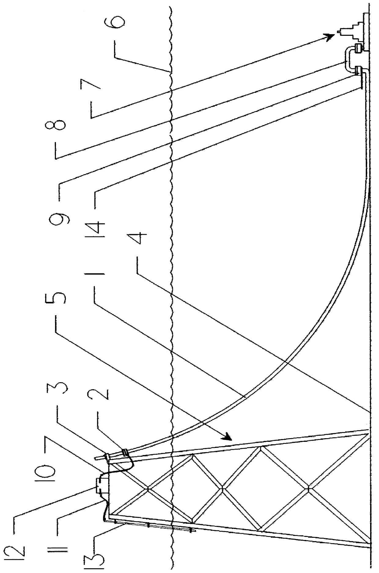
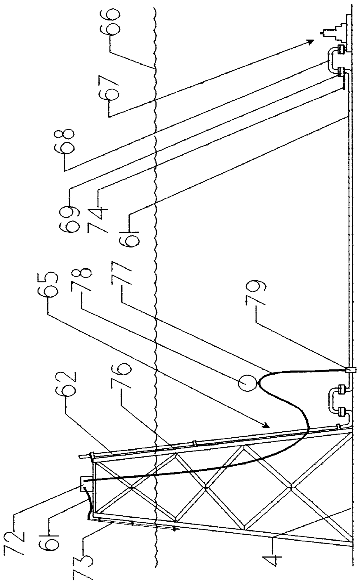
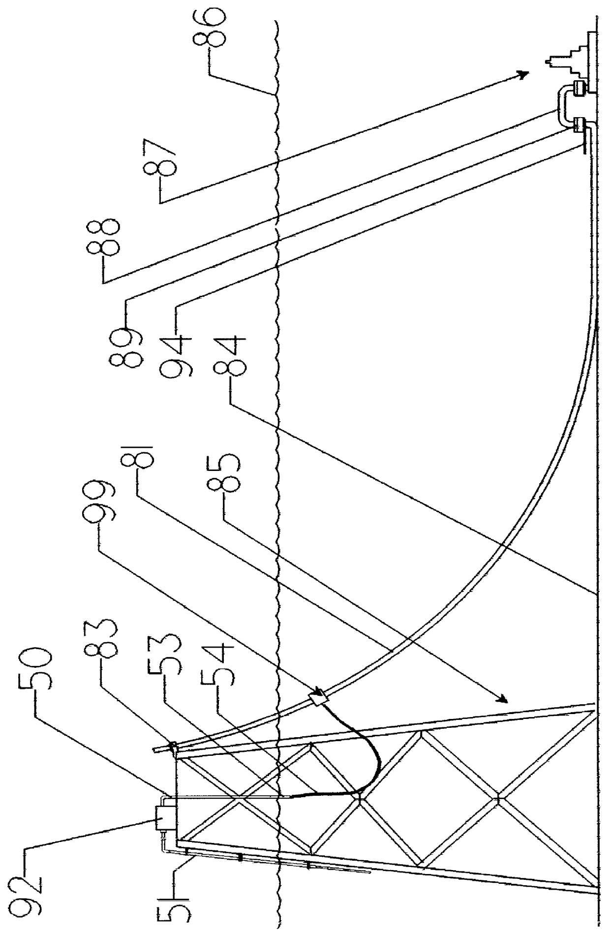
Heating pipelines is only cost-effective if the thermal resistance between the heating element and the fluid in the pipeline is low compared to the thermal resistance between the heating element and the environment. If the pipeline is submerged, the available ways to achieve this are constrained by the electrical and thermal conductivity, and hydrostatic pressure of sea water. This is further complicated by the high cost of time during offshore pipeline installation. Many of the methods for heating onshore pipelines were conceived to overcome the problem of electric shock. In this invention the electrical conductivity of sea water is used as a benefit by serving as an inherently safe ground and return current path. An electrically conductive pipeline is electrically insulated from the surrounding sea water with a waterproof coating and the pipeline conducts alternating current that generates impedance heating in the pipe. Preferably one coating will electrically and thermally insula...


PUM


Abstract

A marine pipeline comprising (a) pipe, (b) a coating that electrically insulates the pipe from sea water, and (c) an alternating current heating circuit comprising the pipe in series with ambient sea water, wherein the heat generated by alternating current flowing in the pipe is for improving flow of fluids through the pipeline. A marine pipeline comprising: a) pipe, b) a coating that electrically insulates the pipe from ambient sea water, and c) an alternating current heating circuit that is grounded to the ambient sea water and comprises the pipe in series with a return conductor, wherein the heat generated by the alternating current flow in the pipe is for improving flow of fluids through the pipeline.

Description

1. Field of the InventionThis invention relates to heated offshore pipelines, more particularly to pipelines electrically heated by AC current flowing through a pipeline made of electrically conducting pipe that is electrically insulated from the sea water with a waterproof coating.2. Related ArtThe use of the technique known as "subsea", or "offset" production to produce offshore oil and gas from offshore reservoirs is increasing. This technique employs small, submerged pipelines known as "flow lines" that are laid along relatively short routes between the submerged wellheads and a gathering point such as a nearby platform. For a variety of reasons it will often be beneficial or necessary to take measures to maintain high temperatures in the fluid flowing in subsea flow lines, One way to this is done is to add insulation.Because flow lines are generally small, relatively short, and often in deep water, installation from reel barges is often faster and less expensive than installati...

Claims


Application Information

Patent Timeline
IPC IPC(8): E21B17/01E21B43/00E21B43/01E21B17/00F16L59/00F16L53/00F16L59/14F16L53/37
CPCE21B17/01E21B17/015F16L59/14F16L53/007E21B43/01F16L53/37
Inventor SUMNER, GLEN R.
Owner SUMNER GLEN R
Why Eureka
Try Eureka