Bottle can member, bottle, and thread forming device

a technology of thread forming device and bottle can, which is applied in the field of metal bottles, can solve the problems of broken bridge, reduced airtight condition, and section in which a thread is formed insufficiently, and achieve the effect of smoothly detaching the cap

Active Publication Date: 2010-09-21
UNIVERSAL CAN CORP
View PDF24 Cites 72 Cited by
  • Summary
  • Abstract
  • Description
  • Claims
  • Application Information

AI Technical Summary

Benefits of technology

[0033]Also, other object of the present invention is to provide a metal bottle can which has a folding rigidity in which the mouth section of the metal bottle can be sealed by the cap reliably.
[0057]According to the bottle according to the present invention, the height of the thread in the thread section which is disposed on the mouth section is approximately equal to the height therearound; therefore, if the cap is put there, the cap is not depositioned due to a positive pressure in the bottle can member, nor the bridge is not broken. In addition, it is possible to obtain a desirable bottle by which it is possible to put and detach the cap smoothly.

Problems solved by technology

However, in a conventional bottle can member 1, if the effective thread number n the thread section 3 which is disposed in the mouth section 2 of the bottle can member 1 is approximately 1.5 to 1.7, a section in which there are two threads which are disposed toward a tip section from a base end section of the mouth section 2 and a section in which there is only one thread occur; thus, such a difference of the threads causes a problem.
That is, there has been a problem in that a bridge is broken.
Therefore, unequal sealing capability occurs in a circumferential direction; thus, there is a concern that there is a reduced airtight condition.
In such a case, a relative position between the position for compressing the cap by a thread forming roller and a position of a starting point W1 in a complete thread section W is shifted in an axial direction undesirably; thus, there is a section in which a thread is formed insufficiently.
If there is not a case in which a bridge is broken in a cap 5 due to an inner pressure of the bottle, an interval therebetween extends if the interval between the cap thread section 7 of the cap 5 and a ceiling surface is long; thus, there is a problem that a contact of the cap decreases.
In such a case, there is a problem in that it bends undesirably because of insufficient rigidity against the pressing force to the cap 103 in a step for putting the cap 103.
Also, if the effective thread number is increased to be 2.5 or more so as to enhance the engaging force, there is a problem in that a torque for opening the cap needs to be greater.
However, if the thread number of the thread section is approximately 1.7, as shown in FIG. 20, there is a problem in that there is a section in which there two tread sections 203 on an peripheral surface of the mouth section 202 and there is a section in which there is only one thread section 203; thus, such a difference between the thread sections causes a problem.
Thus, there is a problem in that there is a so-called a broken bridge.

Method used


Image

  • Bottle can member, bottle, and thread forming device
  • Bottle can member, bottle, and thread forming device
  • Bottle can member, bottle, and thread forming device

Examples


first embodiment

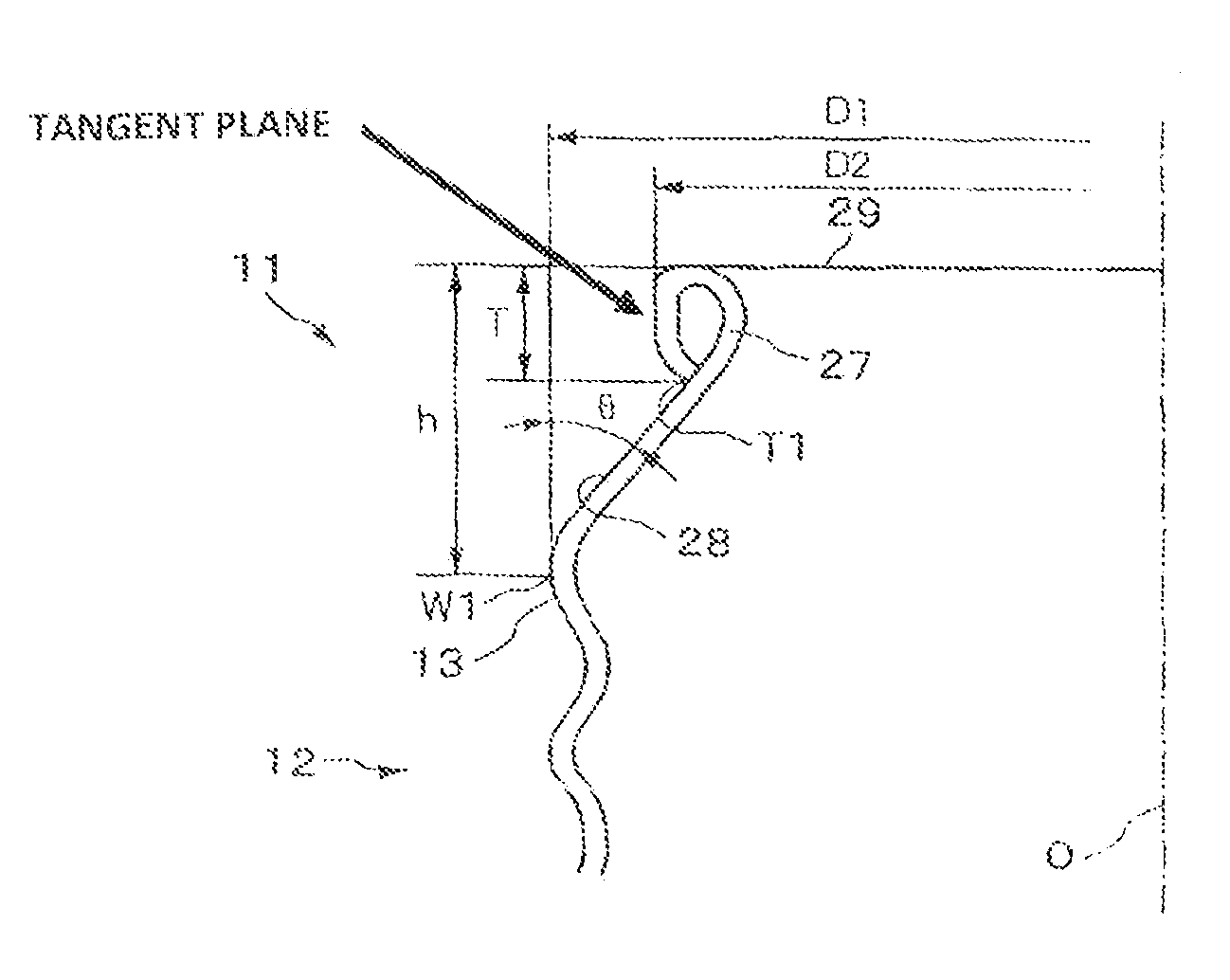
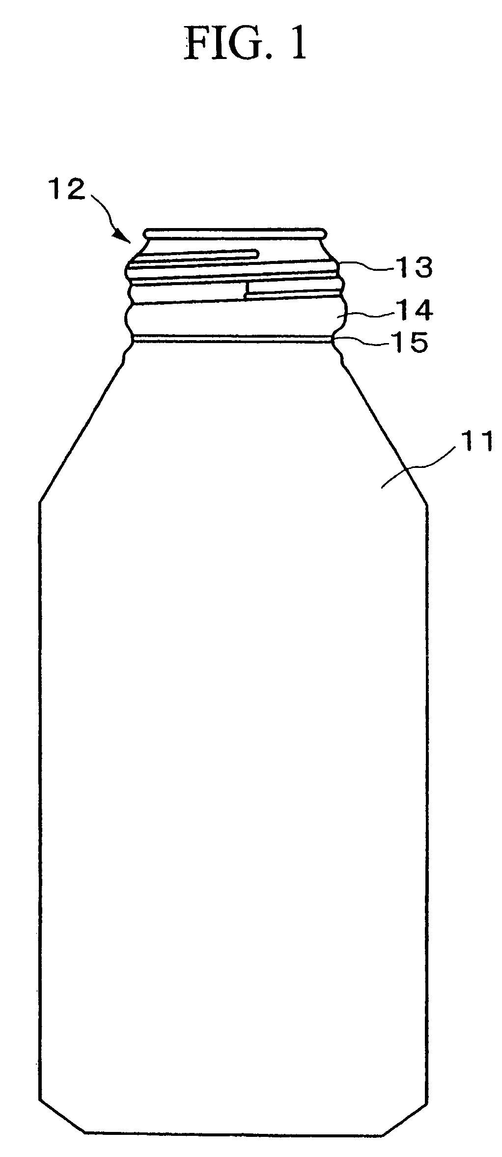
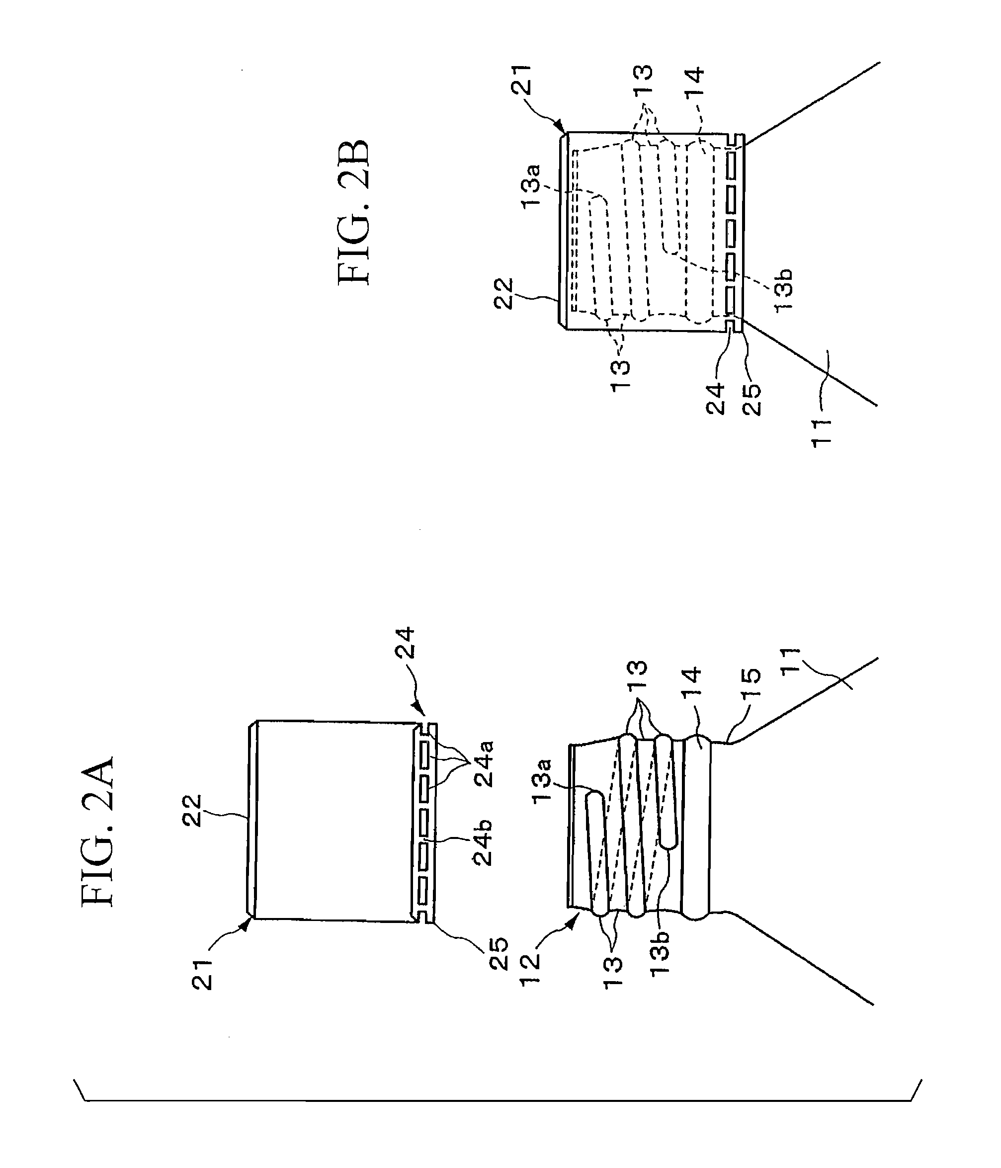
[0082]Hereinafter, the embodiments of the present invention are explained with reference to the drawings. FIGS. 1 to 5 are views for showing a bottle can member and a bottle in which a cap is put on the bottle can member. FIG. 1 is a view for showing an entire bottle can member. FIG. 2 is a view for explaining FIGS. 2A and 2B illustrate a relationship between the bottle can member and the cap. FIG. 3 is a cross section for explaining steps for putting the cap on the bottle can member. FIG. 4 is an enlarged view for showing the bottle in which the cap is put on the bottle can member. FIG. 5 is an enlarged cross section for the mouth section of the bottle can member.

[0083]The bottle can member 1 according to the present embodiment serves for filling a carbonated beverage and a fruit beverage thereinside which is made of an aluminum member or an aluminum alloy such that the mouth section 12 is formed on an upper section of the bottle can member 11 as shown in FIG. 1.

[0084]A thread sec...

second embodiment

[0150]FIG. 18 is an enlarged view for explaining an important part which shows a thread section which is disposed in the mouth section of the bottle can member according to the present invention.

[0151]If the thread section 203 which has a thread number 2.2 is formed on the mouth section 202 of the bottle 201, there are two stages of thread except the thread area in which there are three stages of thread.

[0152]The present embodiment takes the thread section 203 in which there are two stages of thread into consideration. Here, the height of the thread 301 in the first stage is formed so as to be lower than the height of the thread 302 in the second stage.

[0153]That is, the thread 301 in the first stage is formed so as to be in an area except an area (L) in which there are three stages and an incomplete thread section of the thread end section such that the height of the thread 301 in the first stage should be lower than the thread 302 in the second stage only by a dimension A. Therefo...


PUM


Abstract

An effective thread number in the thread section which is disposed on the mouth section of the bottle is formed to be 2.2. That is, the thread section is formed such that the thread section 13 should serve effectively in the mouth section such that an interval between a start position and an end position should be 2.0 to 2.5. In the bottle can member 11 which has such a thread section, an outer diameter of the thread section which is formed on the mouth section is 28 to 38 mm. Also, the thickness of the mouth section is 0.25 to 0.4 mm. The thread section which has the effective thread number 2.0 to 2.5 is formed by eight-thread per inch pitch. By doing this, it is possible to put the cap desirably.

Description

CROSS-REFERENCE TO PRIOR APPLICATION[0001]This is a U.S. national phase application under 35 U.S.C. §371 of International Patent Application No. PCT / JP02 / 13840 filed Dec. 27, 2002, and claims the benefit of Japanese Patent Application Nos. 2001-401686 filed Dec. 28, 2001; 2002-193465 filed Jul. 2, 2002; 2002-197799 filed Jul. 5, 2002 and 2002-233917 filed Aug. 9, 2002 which are incorporated by reference herein. The International Application was published in Japanese on Jul. 17, 2003 as WO 03 / 057572 A1 under PCT Article 21(2).TECHNICAL FIELD[0002]The present invention relates to a metal bottle can, a thread forming device in which a thread section is formed on a mouth section. Furthermore, the present invention relates to a method for forming a mouth section.BACKGROUND ART[0003]A so-called bottle can member 1 which is formed by a drawing operation for a metal bottle member has a thread section 3 on a mouth section 2 and an outer periphery on an aperture section of the bottle can memb...

Claims


Application Information

Patent Timeline
Patent Type & Authority Patents(United States)
IPC IPC(8): B65D1/12B65D1/02B65D41/34B67B3/18
CPCB65D1/0246B67B3/18B65D41/3447Y10S72/715B65D1/02B65D41/04B21D51/38
Inventor HANAFUSA, TATSUYAITO, RYOICHIHOSOI, MASAHIROTASAKA, NAOKI
Owner UNIVERSAL CAN CORP
Why Eureka
Try Eureka