Ophthalmic apparatus

a technology of ophthalmology and ophthalmology, applied in the field of ophthalmology, can solve the problem of long time for testing,

Inactive Publication Date: 2010-09-28
NIDEK CO LTD
View PDF10 Cites 3 Cited by
  • Summary
  • Abstract
  • Description
  • Claims
  • Application Information

AI Technical Summary

Benefits of technology

[0007]An object of the invention is to overcome the problems described above and to provide an ophthalmic apparatus which allows for easy checking of a difference between visibilities in scotopic vision and in photopic vision and allows an examinee to recognize the necessity to change a corrective diopter in the scotopic vision with respect to a corrective diopter in the photopic vision.

Problems solved by technology

However, it is necessary to wait for adaptation of the pupil size to the ambient brightness, and therefore, the test takes a long time and an immediate comparison of visibilities in the scotopic vision and in the photopic vision cannot be performed.

Method used


Image

  • Ophthalmic apparatus
  • Ophthalmic apparatus
  • Ophthalmic apparatus

Examples


Embodiment Construction

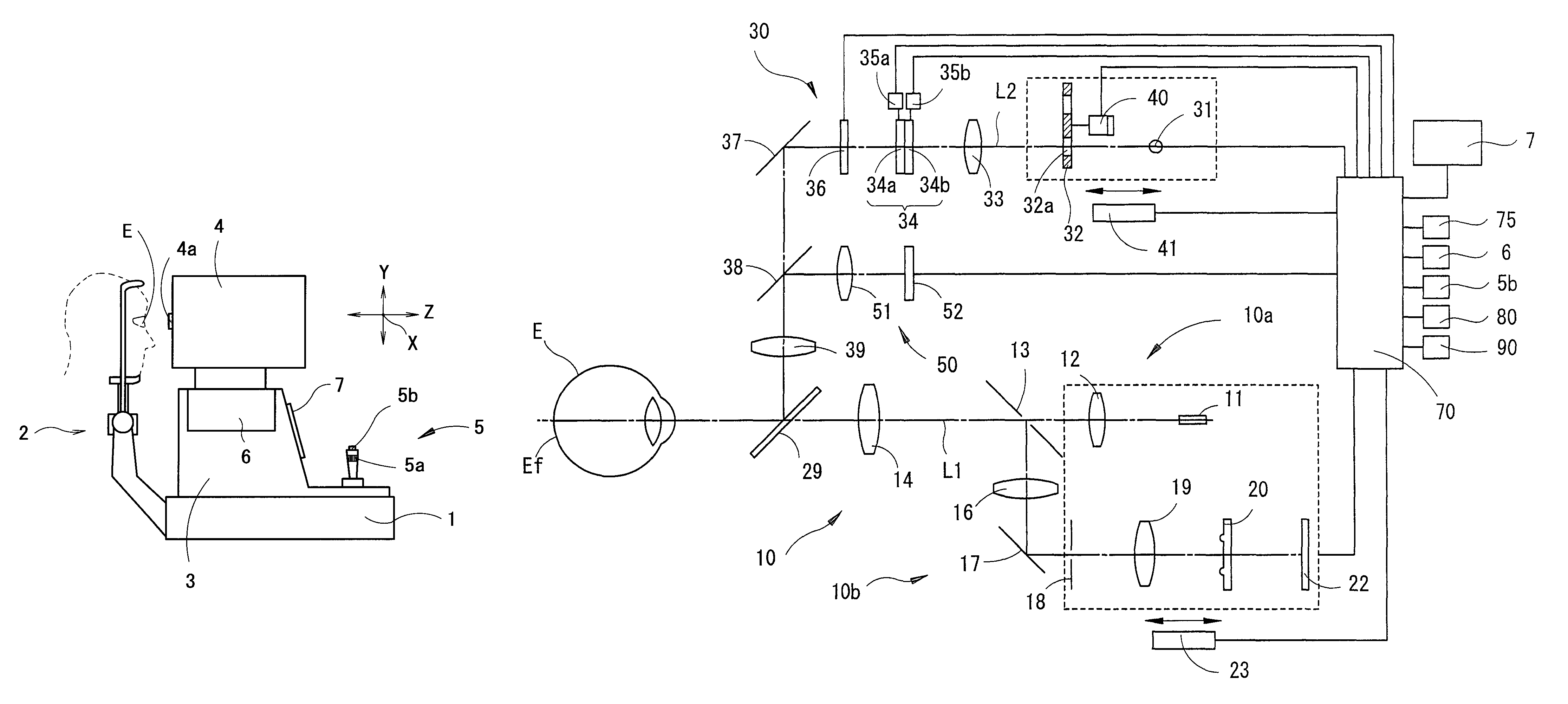
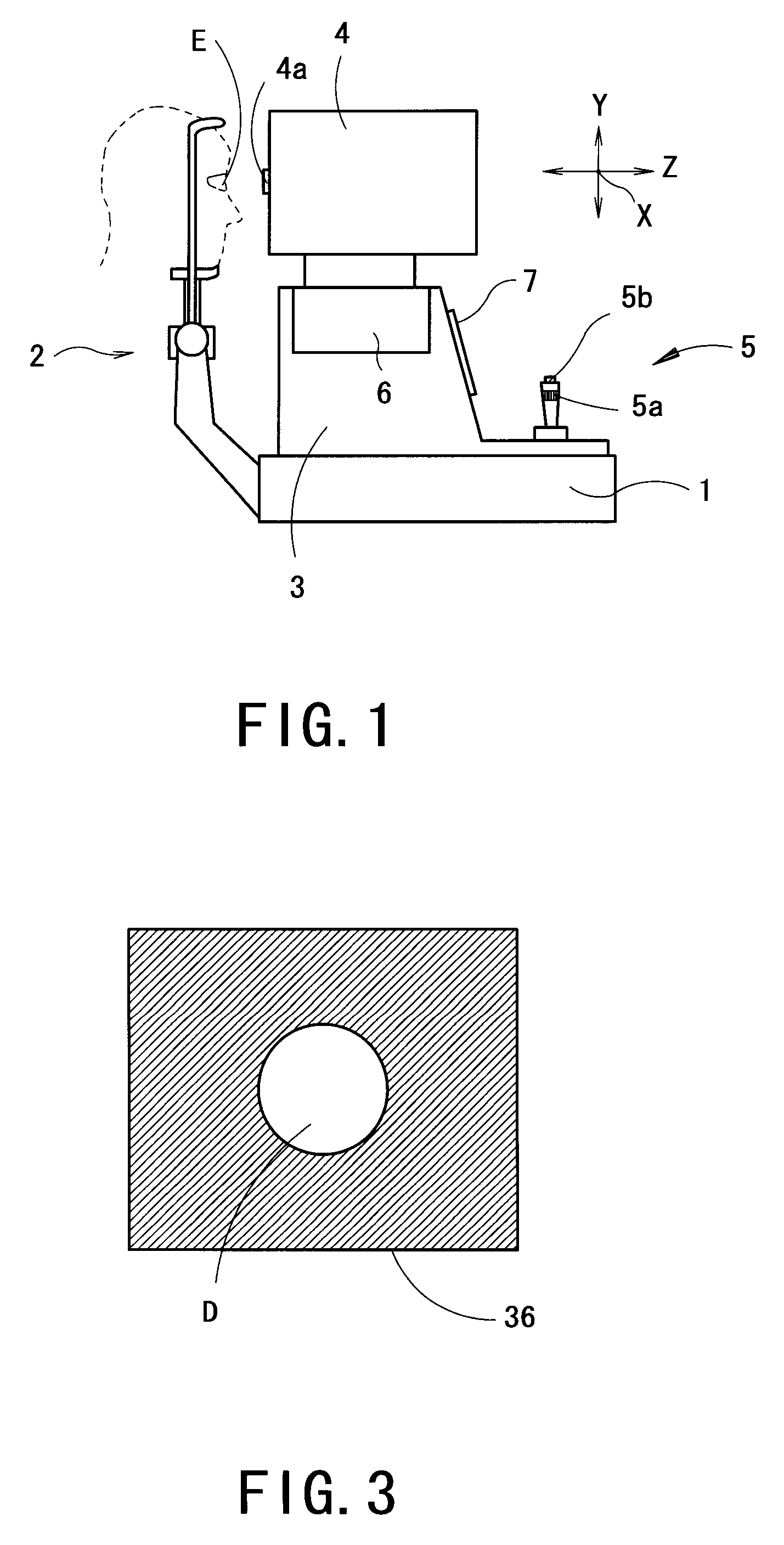
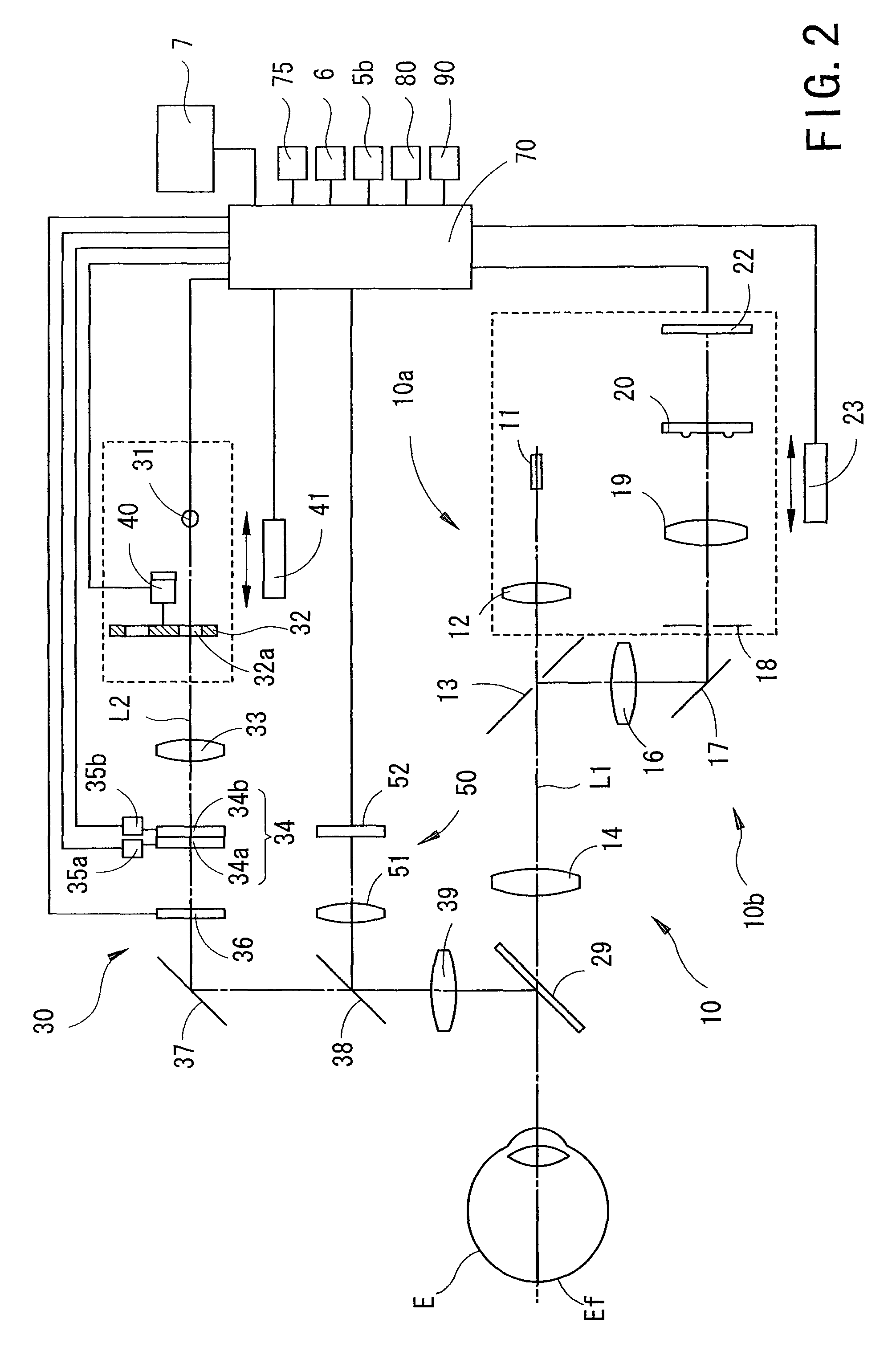
[0018]A detailed description of one preferred embodiment of an ophthalmic apparatus embodied by the present invention is provided below with reference to the accompanying drawings. FIG. 1 is a schematic external view of an eye refractive power measurement apparatus. The apparatus includes a base 1, a face supporting unit 2 attached to the base 1, a mobile base 3 movable on the base 1, and a measurement unit 4 movable on the mobile base 3 and housing an optical system to be described later. The measurement unit 4 is moved in a right / left direction (an X direction), an up / down direction (a Y direction), and a back / forth direction (a Z direction) with respect to an examinee's eye E by an XYZ driving unit 6 provided to the mobile base 3. The mobile base 3 is moved in the X and Z directions on the base 1 by operation of a joystick 5. The measurement unit 4 is moved in the Y direction by means of the XYZ driving unit 6 through rotating operation of a rotation knob 5a by an examiner. A mea...


PUM


Abstract

An ophthalmic apparatus has an optical system for presenting a target to an examinee's eye through a lens, an optical system placed in an optical path of the target presenting optical system, for correcting a refractive error of the eye seeing the target, a switching unit arranged to switch an aperture size of a diaphragm, which is placed in a position substantially conjugate with a pupil with respect to the lens, between a first size corresponding to a pupil size of the eye in photopic vision and a second size larger than the pupil size in scotopic vision, an inputting unit arranged to generate a signal for switching the aperture size between the first and second sizes, and a control unit arranged to control driving of the switching unit based on the signal from the inputting unit to switch the aperture size between the first and second sizes.

Description

BACKGROUND OF THE INVENTION[0001]1. Field of the Invention[0002]The present invention relates to an ophthalmic apparatus such as an eye refractive power measurement apparatus which measures eye refractive power of an examinee's eye.[0003]2. Description of Related Art[0004]Conventionally, in order to obtain an estimate of a corrective diopter when prescribing a corrective such as spectacles, there is used an eye refractive power measurement apparatus which projects light of a measurement target onto a fundus of an examinee's eye, detects the light reflected from the fundus by a photodetector, and measures eye refractive power of the eye based on a result of the detection (see Japanese Patent Application Unexamined Publication No. 2007-89715 (corresponding to U.S. Pat. No. 7,452,078)). In addition, there is known an eye refractive power measurement apparatus in which a target presenting optical system includes an optical system for correcting a spherical refractive error and an astigm...

Claims


Application Information

Patent Timeline
Patent Type & Authority Patents(United States)
IPC IPC(8): A61B3/10
CPCA61B3/0091A61B3/103A61B3/12A61B3/032
Inventor KAWAI, NORIJI
Owner NIDEK CO LTD
Why Eureka
Try Eureka