Optical fibre connection device

a technology of optical fibre connection and optical fibre, applied in the direction of optics, fibre mechanical structures, instruments, etc., can solve the problems of relative cost and slow installation, and achieve the effect of facilitating firm holding of the connector

Inactive Publication Date: 2010-09-28
COMMSCOPE CONNECTIVITY BELGIUM BVBA
View PDF15 Cites 57 Cited by
  • Summary
  • Abstract
  • Description
  • Claims
  • Application Information

AI Technical Summary

Benefits of technology

[0019]The optical fibre cable connection end may comprise one or more tongues arranged to be deflectable to engage with the jacket of an optical fibre cable, upon insertion of an optical fibre cable into the optical fibre cable connection end, in order to improve strain relief and prevent torsion of the optical fibre cable. The one or more tongues may comprise tongue pairs which are arranged to be diametrically opposed.
[0029]The interior surface of the cap may be contoured to match the exterior shape of the connector to facilitate firm holding of the connector within the shells.
[0030]One of the shells may comprise upstanding retaining formations located on the interior of the shell arranged to engage with complementary formations on the exterior of the connector to hold the connector firmly in place and to prevent relative rotation of the connector with respect to the shell when the connector is held within the shell.
[0042]The second access position may provide an access position which is away from interference by the support.

Problems solved by technology

Screw-threaded connectors and pulling caps for optical fibre cables are described in U.S. Pat. Nos. 6,579,014 and 6,648,520 of Corning Cable Systems, but these are relatively expensive and slow to install, which is a serious commercial handicap when large numbers of such connections are to be made.

Method used


Image

  • Optical fibre connection device
  • Optical fibre connection device
  • Optical fibre connection device

Examples


Embodiment Construction

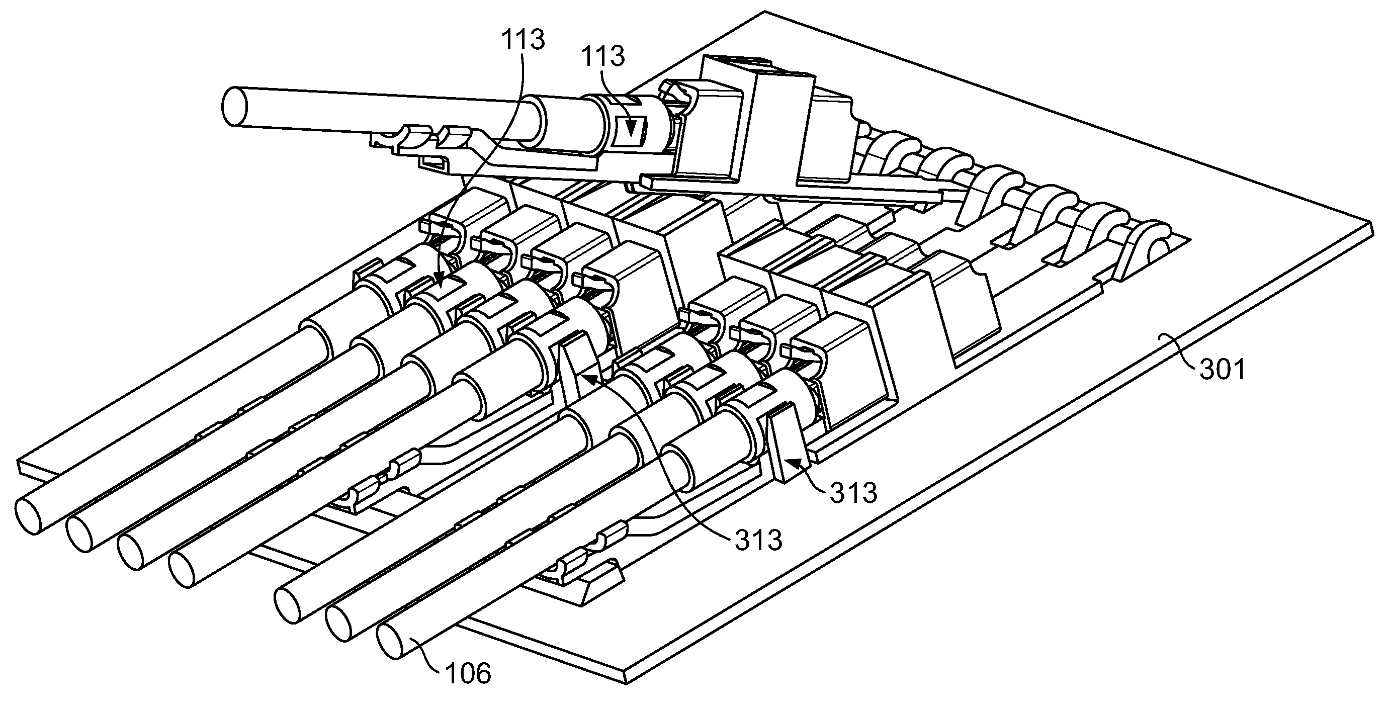
[0082]Various types of optical fibre connection devices 103, 200, 300 according to one or more aspects of the present invention are shown in the accompanying figures. Let us first consider embodiments of the optical fibre connection device 103 according to the first aspect of the invention (FIGS. I-1 to I-2).

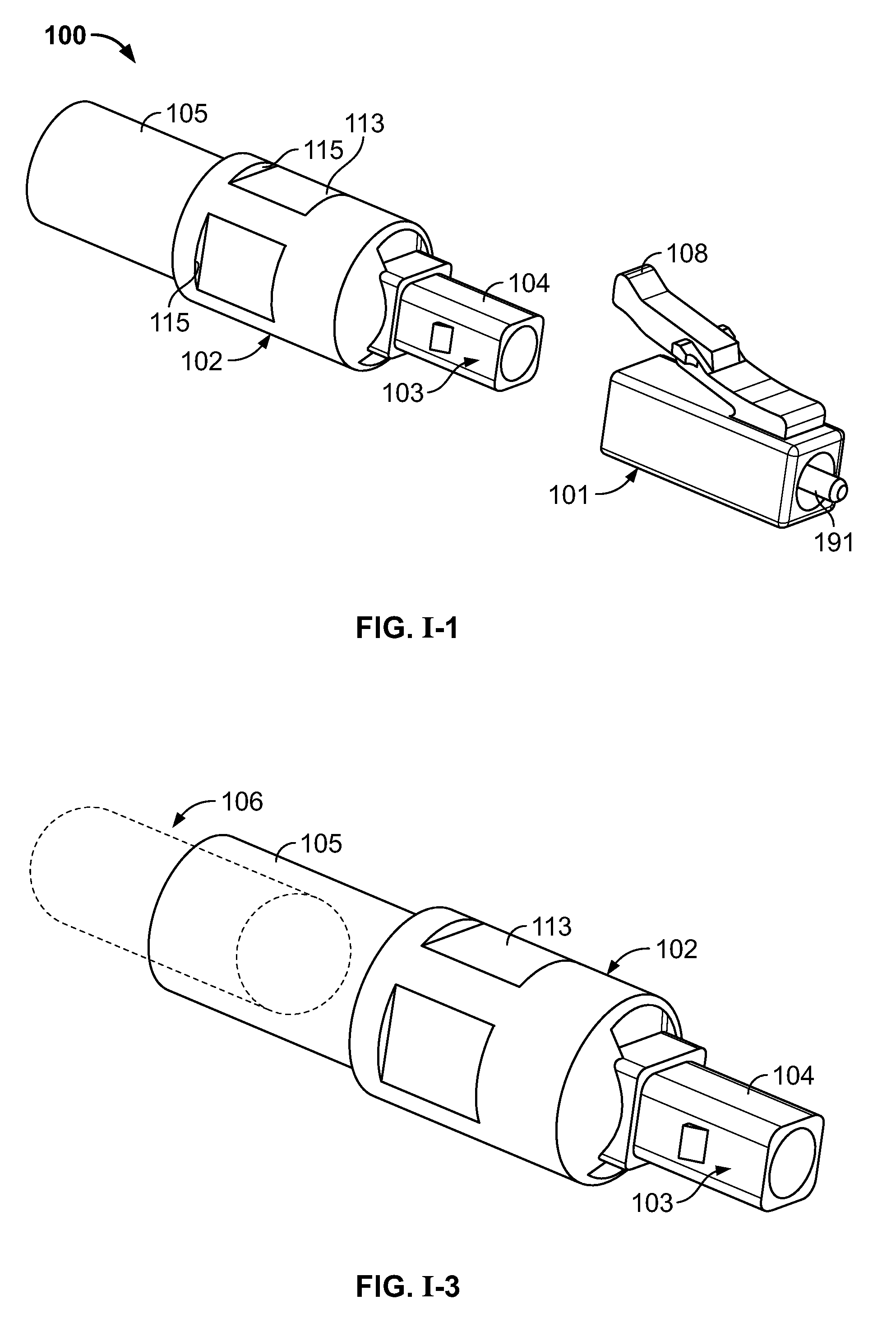
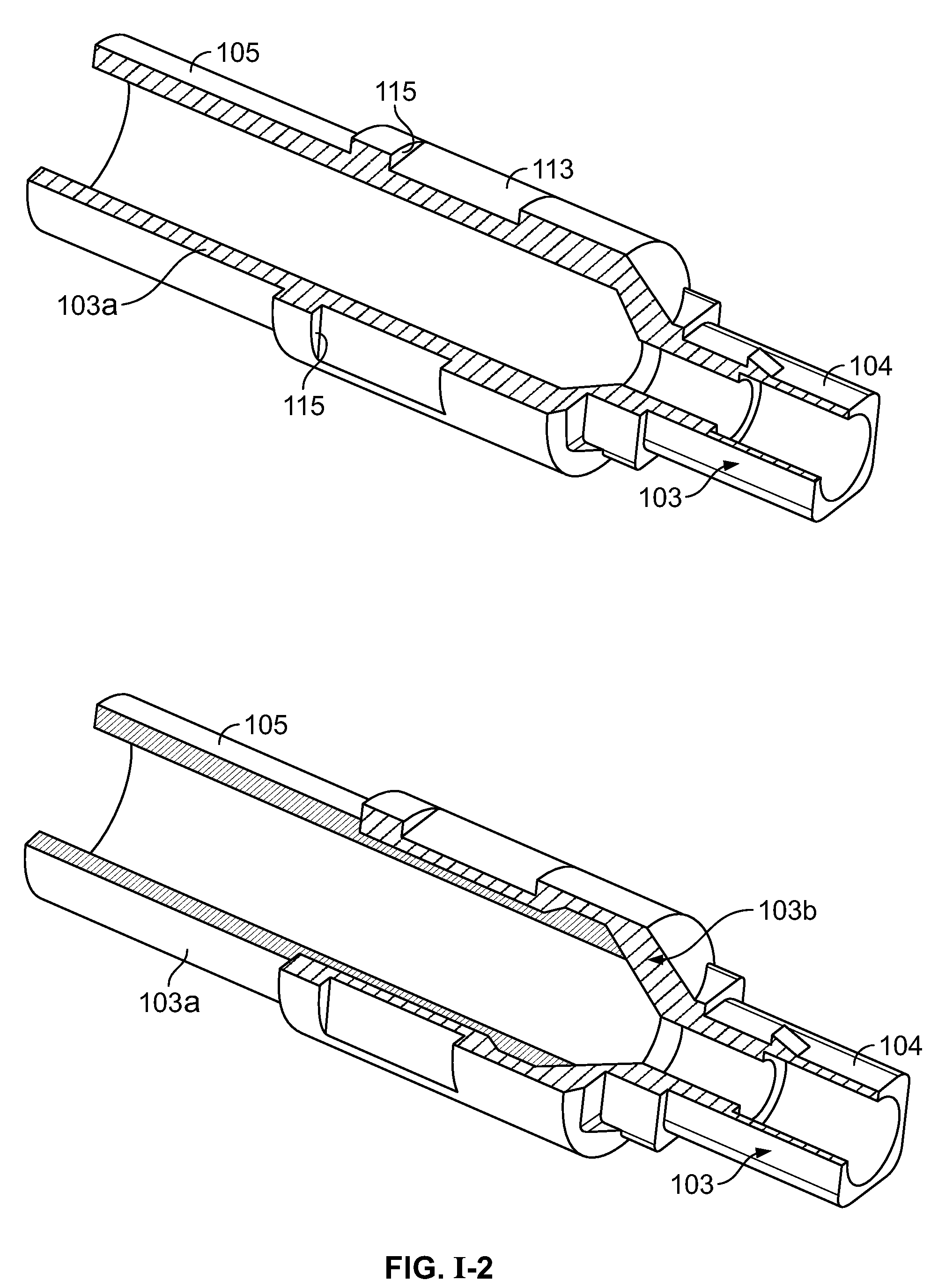
[0083]Examples of optical fibre connection devices 103, according to the first aspect of the invention are illustrated in FIGS. I-1 to I-20. These embodiments relate to a slim termination and strain relief device for connectorized drop cables in which a rear part 103 of a known multi-part LC connector (100, FIG. I), has a body 102, which has a section 105 which can be crimped or otherwise connected to a cable 106 by any type of mechanical fixture.

[0084]It can be seen from FIG. I-1 that the multi-part LC connector 100 comprises two parts which can be releasably snap-fitted together; a front terminal part 101 and a rear cable connection part 103. The front terminal part 101 houses...


PUM


Abstract

The present invention provides an optical fiber connection device comprising a part (103) of a screw-threadless multi-part (101, 103) optical fiber cable connector (100), the multi-parts (101, 103) of the connector (100) being inter-connectable, the part (103) comprising a body (102), the body (102) comprising: an optical fiber cable connection end (105) for connection with an optical fiber cable (106); a part connection end (104) for connection with another part (101) of the multi-part optical fiber cable connector (100); and one or more formations (113) adapted to co-operate with a retainer (213, 313) in a mounting (200, 300) for the connector (100), the mounting (200, 300) used to retain the optical fiber cable (106) and the connector (100) when the optical fiber cable (106) is connected to the optical fiber cable connection end (105) of the body (102), the formations (113) adapted to co-operate with the mounting retainer (213, 313) to resist rotational and / or axial movement of the connector (100) when the connector (100) is assembled with an optical fiber cable (106) and the other parts (103, 101) of the connector (100) and mounted in the mounting (200, 300).

Description

FIELD OF THE INVENTION[0001]This invention relates to new optical fibre connection devices for making and facilitating optical fibre connections, especially drop cable connections from a telecommunications optical network to subscribers, sometimes referred to a “Fibre To The Home” (FFTH). The devices facilitate physical connection of optical fibre cables in an optical fibre transmission network. The new optical fibre connection devices according to this invention include without limitation:[0002](I) new derivatives of known LC connectors or other optical fibre cable connectors known per se, these connectors facilitating the physical connection of an optical fibre to a connection terminal in the optical fibre network;[0003](II) pulling caps for pulling connectorised optical fibre cables through ducts leading to apparatus in the optical fibre network to which the cables are to be connected. These connectorised optical fibre cables are optical fibre cables which are already connected t...

Claims


Application Information

Patent Timeline
Patent Type & Authority Patents(United States)
IPC IPC(8): G02B6/36
CPCG02B6/3825G02B6/3869G02B6/4465G02B6/3897G02B6/3887G02B6/3893G02B6/3888G02B6/3889G02B6/545G02B6/38G02B6/44
Inventor LEEMAN, SAMPEETERS, ERIKJUNIUS, ERWINGOOSSENS, SANDRA
Owner COMMSCOPE CONNECTIVITY BELGIUM BVBA
Why Eureka
Try Eureka