Method and system for providing power factor correction in a power distribution system

a power distribution system and power factor technology, applied in the direction of ac network circuit arrangement, circuit arrangement, instruments, etc., can solve the problem of additional real power loss, time difference (phase delay) between current and voltage waveform, and undesirable portion size of power distribution network

Active Publication Date: 2010-09-28
S&C ELECTRIC
View PDF29 Cites 86 Cited by
  • Summary
  • Abstract
  • Description
  • Claims
  • Application Information

AI Technical Summary

Problems solved by technology

Real power measures the ability of a network load to perform work in a particular time, and is associated with power consumption by a resistive load.
In a circuit having reactive loads, such as a circuit having capacitive or inductive loads, there may be a time difference (a phase delay) between current and voltage waveforms of the alternating current power.
The additional current may result in additional real power losses caused by the losses of the power transmission lines in conducting the additional current and may require the generating facility to produce more power.
It is undesirable for a power distribution network to have portions with a power factor that is substantially far from unity.
Production of such excess power is inefficient and is inconsistent with policies of conserving energy and preserving environmental resources.
Further, in order to distribute the increased apparent power, the utility may need to build additional infrastructure for networks beyond the networks required for distribution of real power.
Further, consumer utility meters typically measure only real power and consumers are charged for real power consumption.
However, the costs of delivering power determine power rates.

Method used


Image

  • Method and system for providing power factor correction in a power distribution system
  • Method and system for providing power factor correction in a power distribution system
  • Method and system for providing power factor correction in a power distribution system

Examples


Embodiment Construction

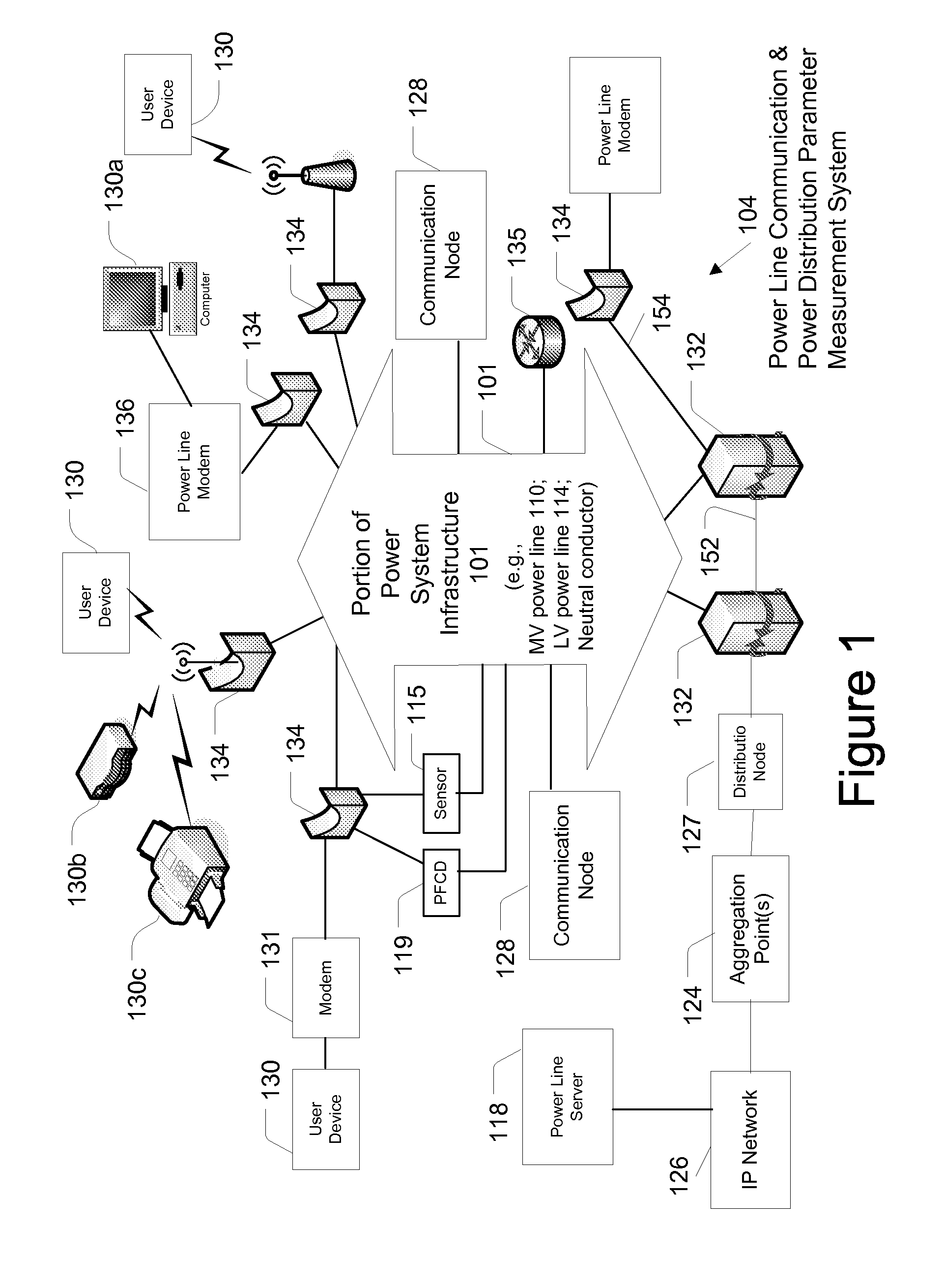
[0021]In the following description, for purposes of explanation and not limitation, specific details are set forth, such as particular networks, communication systems, computers, terminals, devices, components, techniques, data and network protocols, power line communication systems (PLCSs), software products and systems, enterprise applications, operating systems, development interfaces, hardware, etc. in order to provide a thorough understanding of the present invention.

[0022]However, it will be apparent to one skilled in the art that the present invention may be practiced in other embodiments that depart from these specific details. Detailed descriptions of well-known networks, communication systems, computers, terminals, devices, PLCSs, components, techniques, data and network protocols, software products and systems, operating systems, development interfaces, and hardware are omitted so as not to obscure the description of the present invention.

[0023]Communication and Measureme...


PUM


Abstract

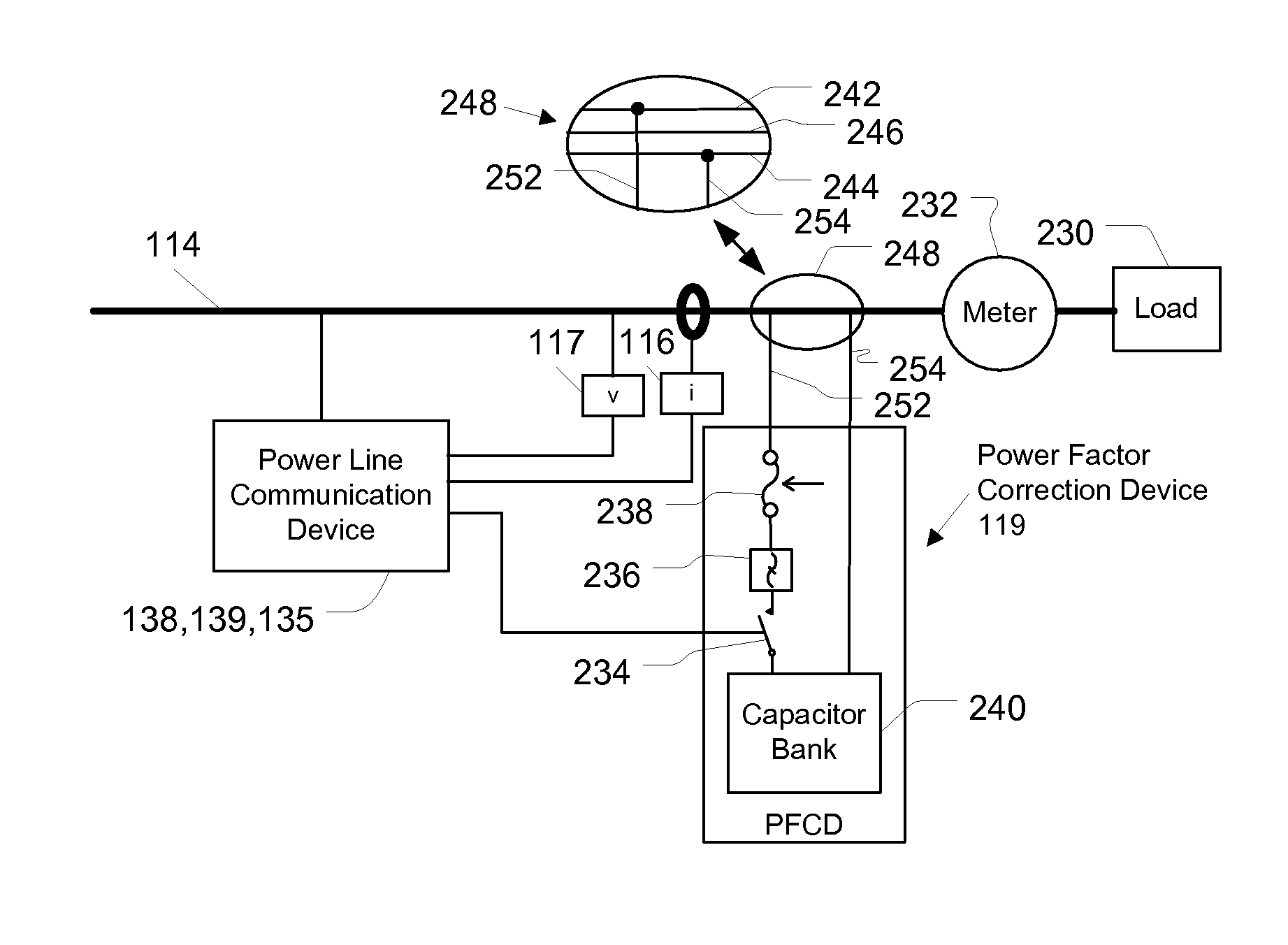
A device for providing power factor correction of a low voltage subnet that includes a low voltage feeder line that is connected to one or more low voltage power supply lines that supply power to one or more customer premises is provided. In one embodiment, the device includes a power factor measurement module configured to measure power parameters for determining a power factor of the power traversing the low voltage subnet; a power factor correction assembly configured to vary a capacitance connected to the low voltage feeder of the low voltage subnet; a controller in communication with the power factor measurement assembly and the power factor correction assembly. The controller may be configured to cause the power factor correction assembly to change the capacitance based on the determined power factor. The controller may form part of a power line communication device configured to provide communications to the one or more customer premises.

Description

CROSS REFERENCE TO RELATED APPLICATIONS[0001]This application is a continuation-in-part of, and claims priority to, U.S. patent application Ser. No. 11 / 555,740 filed Nov. 2, 2006, which is incorporated herein by reference in its entirety.FIELD OF THE INVENTION[0002]The present invention generally relates to methods, systems, and apparatus for efficiently distributing power, and more particularly to methods, systems, and devices for providing power factor correction in a power distribution system.BACKGROUND OF THE INVENTION[0003]Power factor is a ratio of real power to apparent power. Real power measures the ability of a network load to perform work in a particular time, and is associated with power consumption by a resistive load. Apparent power is the product of voltage and current, and may be equal to or greater than the real power due to an impedance of a reactive load. In a purely resistive circuit, voltage and current waveforms are in step, changing polarity at the same instant...

Claims


Application Information

Patent Timeline
Patent Type & Authority Patents(United States)
IPC IPC(8): G05F1/70G08B21/00
CPCH02J3/1828Y02E40/30
Inventor DEAVER, SR., BRIAN J.RADTKE, WILLIAM O.BERKMAN, WILLIAM H.
Owner S&C ELECTRIC
Why Eureka
Try Eureka