Bead attachment

a technology of bead and thread, which is applied in the direction of snap fasteners, buckles, fishing, etc., can solve the problems that the proportion or end of the string cannot be pushed through the hole in the bead, and achieve the effect of reducing the likelihood that the bead can slide on the string, being small and very streamlined

Active Publication Date: 2010-10-05
KAVANAUGH PATRICK JOHN
View PDF138 Cites 17 Cited by
  • Summary
  • Abstract
  • Description
  • Claims
  • Application Information

AI Technical Summary

Benefits of technology

[0011]A hole, channel or aperture formed in the center of the bead when it is closed may be designed to be smaller so as to fit tightly on the string, thereby reducing the likelihood that the bead can slide on the string. It may be desirable to have a bead on a string that does not slide on the string so that other beads on the string are stopped from sliding past a point on the string. Alternatively, the user may tie a knot in the string to keep the bead from slipping past a certain point on the string, similar to, for example, a string of pearls. By sizing the channel so that the string fits tightly within the channel, the user does not have to tie a knot in the string, although a friction fit on the string would allow the bead to be forced or pulled along the string to a new location.

Problems solved by technology

In other words, if knots or obstructions are on the string that portion or end of the string will not be able to be pushed through the hole in the bead.

Method used


Image

  • Bead attachment
  • Bead attachment
  • Bead attachment

Examples


Embodiment Construction

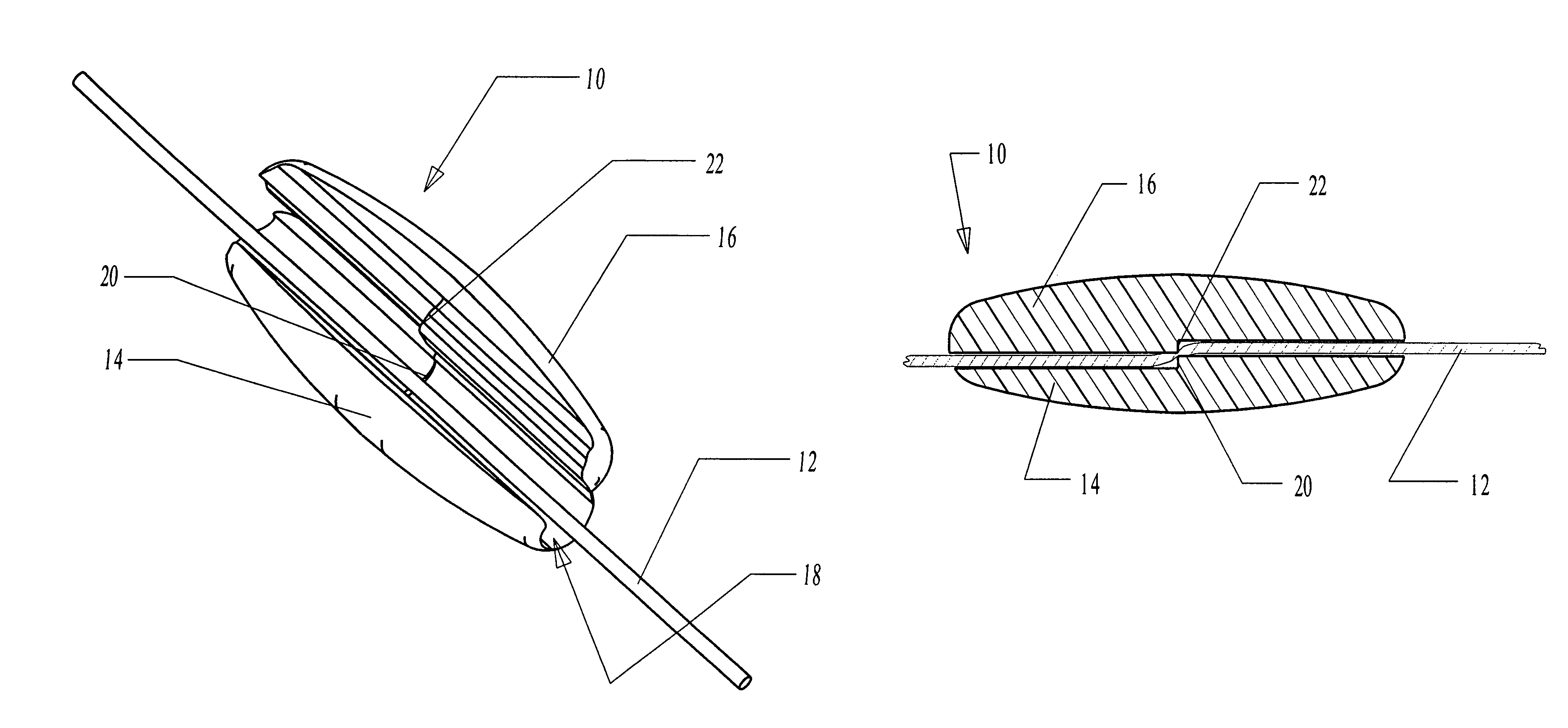
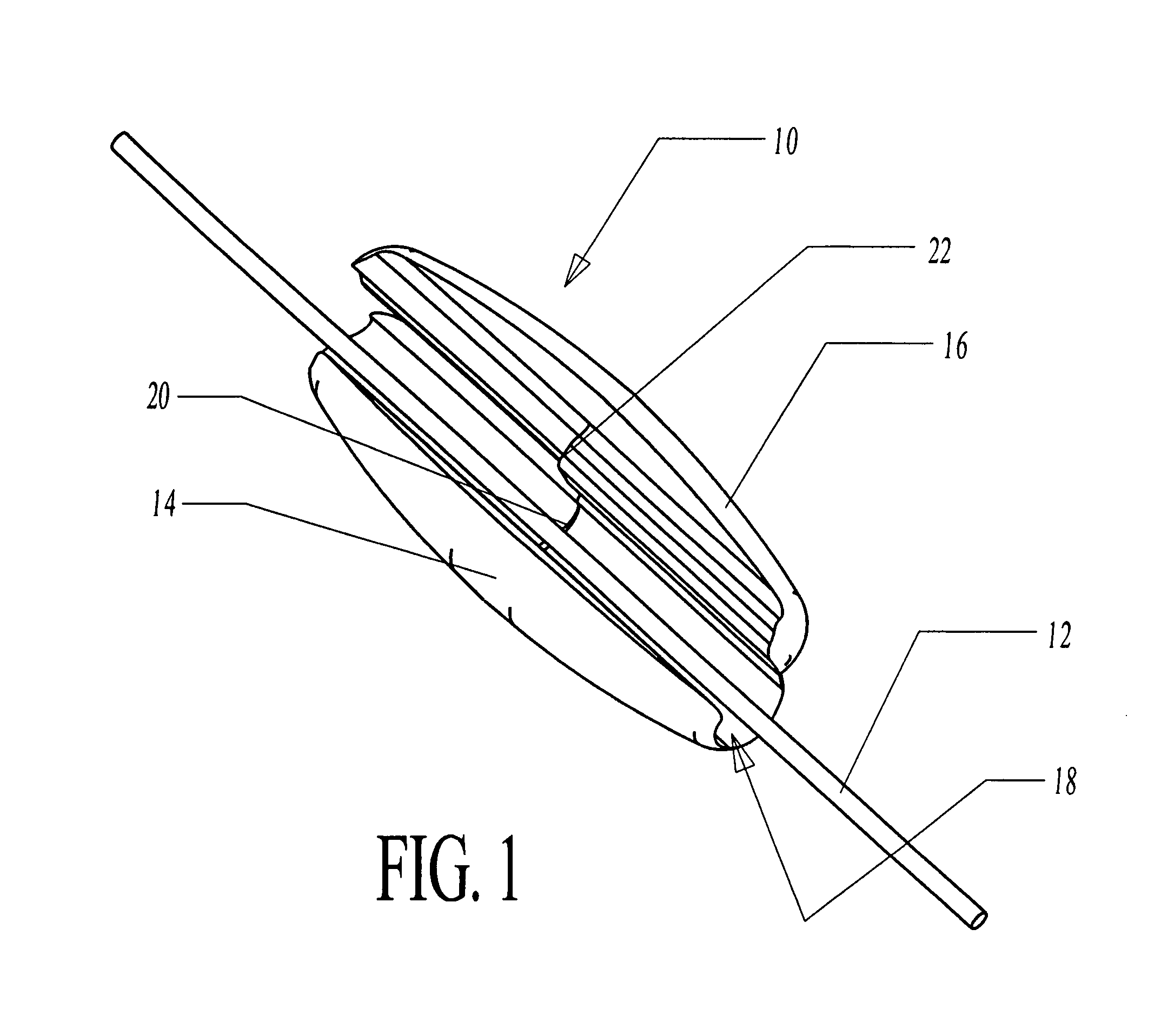
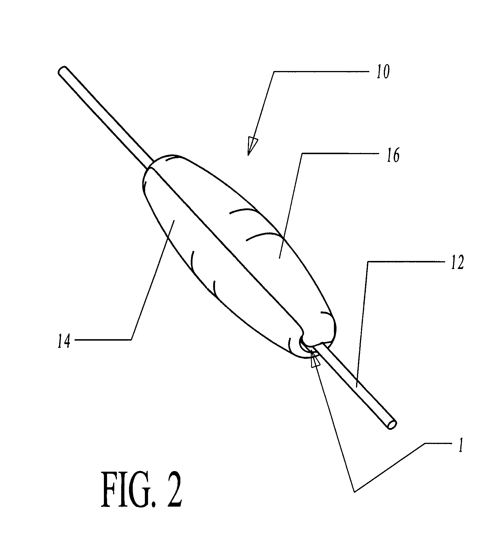
[0025]Those skilled in the art will appreciate that the embodiments of the present invention described herein are exemplary and modifications may be made without departing from the intended scope of the invention. For example, without any limitation intended, although the bead of the present invention is shown in the drawings as being elliptical or spherical, those skilled in the art will appreciate that the bead of the present invention includes alternative shapes and sizes without departing from the intended scope of the invention.

[0026]Referring first to FIGS. 1 and 2, a bead 10 of the present invention is shown having a string 12 positioned within the bead 10. The bead 10 includes a main body 14 and lid 16. A channel 18 is formed in the main body 14 of the bead 10 and is suitable for receiving the string 12 within the channel 18. The channel 18 includes an offset 20 and the interior of the lid 16 likewise includes an offset 22 that is shaped to conform to the offset 20 of the ch...


PUM


Abstract

A device made of a thermoplastic material having two portions connected together with a web or hinge. A first portion forms a main body and the second portion forms a lid or cover. When the lid is aligned and closed onto the main body, the shape of the unitary device may be spherical, elliptical or another shape. The main body allows for one or more lines or strings to rest within a channel formed in the main body parallel to a pivot axis of the hinge so that when the lid is closed into the main body the strings are trapped within the channel of the main body by the lid.

Description

BACKGROUND[0001]1. Field of the Invention[0002]This invention relates generally to a device attachable to a string, rope, wire, cord or other flexible line. More particularly, the attachment device of the present invention is attachable to and will remain on a string without having to thread the string through a hole in the device. The device may be quickly attached to a string by snapping together a top and bottom portion of the device to form the unitary device locked on the string. The device can be used to, for example, mark a location on the string, adorn the string as a decorative bead, or used to bundle two or more strings together by locking a single device on two or more stings.[0003]2. Background of the Invention[0004]A bead typically has a spherical shape with a hole extending through a central axis of the bead. The end of a string may be pushed or threaded through the hole in the bead so that the bead is affixed to the string but can slip along the string. A bead of this...

Claims


Application Information

Patent Timeline
Patent Type & Authority Patents(United States)
IPC IPC(8): A01K95/00A01K91/06A44C25/00
CPCA01K91/047A01K91/06Y10T24/44043Y10T24/3918
Inventor KAVANAUGH, PATRICK JOHN
Owner KAVANAUGH PATRICK JOHN
Why Eureka
Try Eureka