
Tool-free coaxial connector

a coaxial connector and tool-free technology, applied in the direction of connections, basic electric elements, electric devices, etc., can solve the problems of increased assembly cost and inconvenient carrying of different tools by operators, and achieve the effect of improving the conventional coaxial connector

Active Publication Date: 2010-10-05
EZCONN
View PDF5 Cites 117 Cited by
  • Summary
  • Abstract
  • Description
  • Claims
  • Application Information

AI Technical Summary

Benefits of technology

[0006]A primary object of the present invention is to provide a tool-free coaxial connector that can be installed on a free end of a coaxial cable without the need of using any tool, so as to improve the conventional coaxial connector that must be tightened to the coaxial cable using a tool.

Problems solved by technology

Therefore, the assembling cost is increased and an operator has to inconveniently carry different tools along with him.

Method used


Image

  • Tool-free coaxial connector
  • Tool-free coaxial connector
  • Tool-free coaxial connector

Examples


Embodiment Construction

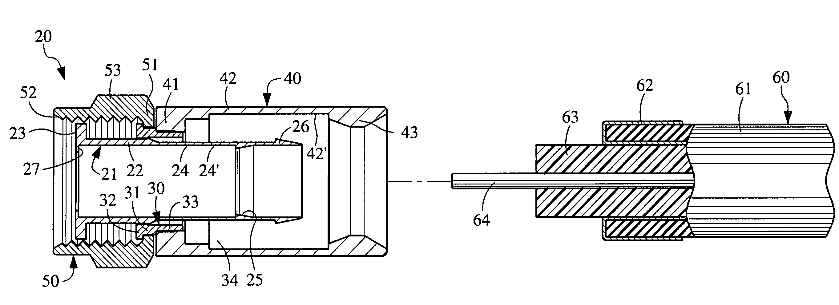
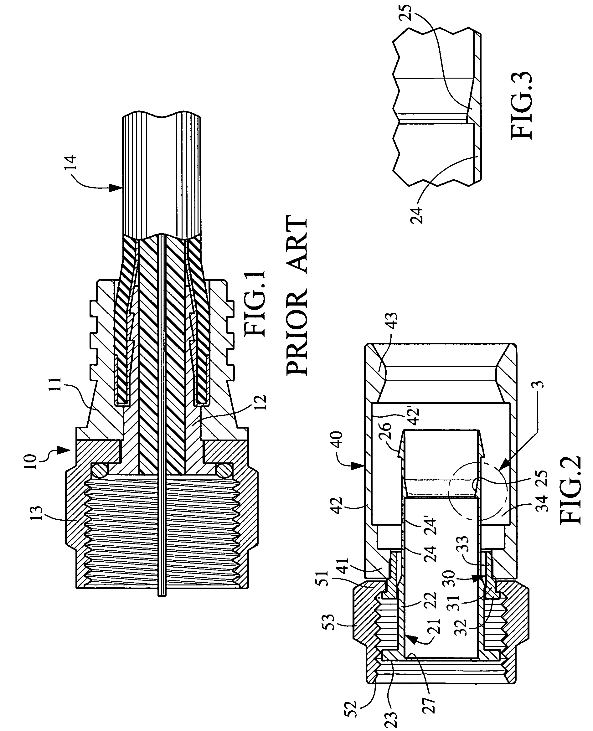
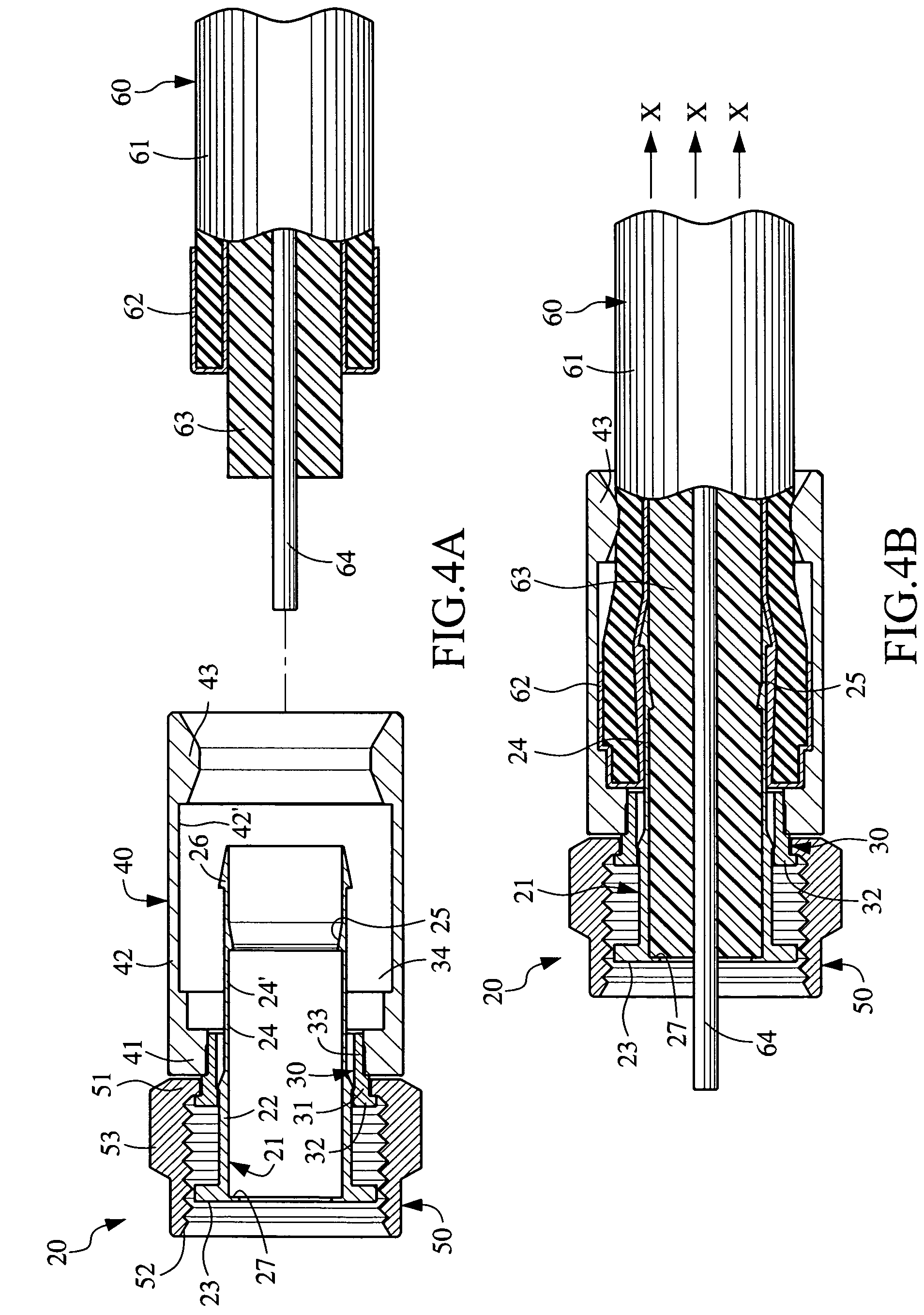
[0014]Please refer to FIGS. 2 and 3. A tool-free coaxial connector according to a preferred embodiment of the present invention is generally denoted by reference numeral 20, and includes an inner sleeve 21, a collar 30, an outer sleeve 40, and a connecting ring 50.

[0015]The inner sleeve 21 includes a main portion 22, a radially outward flange 23 formed around a front end of the main portion 22, and an extended portion 24 extending from a rear end of the main portion 22. The extended portion 24 has an inner diameter the same as the main portion 22, but an outer diameter and a wall thickness smaller than that of the main portion 22. An annular tooth 25 is formed around an inner wall surface 24′ of the extended portion 24 of the inner sleeve 21, such that points of the tooth 25 are directed toward a front end of the coaxial connector 20. An outer wall surface around a rear open end of the extended portion 24 is formed into a circle of radially raised and rearward declined slope 26.

[001...


PUM


Abstract

A tool-free coaxial connector includes an outer sleeve, an inner sleeve coaxial with the outer sleeve, and an annular tooth provided around an inner wall surface of the inner sleeve. The inner sleeve can receive a central conductor and an insulating spacer of the coaxial cable therein, and the outer sleeve can receive a braided metal sheath and an insulating sheath of the coaxial cable therein. When a stripped free end of the coaxial cable is inserted into the coaxial connector, the inner sleeve is forced into between the insulating spacer and the braided metal sheath, and the annular tooth is tightly engaged with the insulating spacer; and when the coaxial cable is rearward pulled, the inner sleeve is rearward moved from a first to a second position and the insulating sheath of the coaxial cable is pressed against an annular rib in the outer sleeve.

Description

FIELD OF THE INVENTION[0001]The present invention relates to a tool-free coaxial connector that can be installed on a free end of a coaxial cable without the need of using any tool.BACKGROUND OF THE INVENTION[0002]A coaxial connector is well-known in the technological field of coaxial cable transmission. Typically, an F-type coaxial connector is screwed to a mating interface connector, so that a coaxial cable connected to the F-type coaxial connector can be electrically connected to various kinds of electronic devices, such as a television set, a CB (citizen's band) radio, an FM (frequency modulation) radio, and other amateur wireless systems.[0003]FIG. 1 is a sectional view of an F-type coaxial connector 10, being illustrated as a representative example of the conventional coaxial connectors. The F-type coaxial connector 10 includes a collar 11, a cylindrical member 12 coaxially fitted in the collar 11, and a nut-shaped connecting ring 13 rotatably mounted to and end of the cylindr...

Claims


Application Information

Patent Timeline
IPC IPC(8): H01R9/05
CPCH01R9/0524
Inventor CHEN, YI-HSIANG
Owner EZCONN
Features
  • Generate Ideas
  • Intellectual Property
  • Life Sciences
  • Materials
  • Tech Scout
  • Unparalleled Data Quality
  • Higher Quality Content
  • 60% Fewer Hallucinations
Learn More