Imaging lens device and imaging apparatus

a technology of imaging lens and imaging apparatus, which is applied in the field of new images, can solve problems such as increasing power consumption, and achieve the effect of reducing power consumption

Inactive Publication Date: 2010-10-05
SONY CORP
View PDF18 Cites 90 Cited by
  • Summary
  • Abstract
  • Description
  • Claims
  • Application Information

AI Technical Summary

Benefits of technology

[0009]In view of the above problems, the invention aims to achieve slim design by employing a light path folding optical system, add a hand-shake correction capability, and lower power consumption.
[0027]Therefore, in the imaging apparatus according to the embodiment and the other embodiment of the invention, the use of the light path folding optical system allows a compact imaging apparatus in the incoming optical axis direction or a slim imaging apparatus, and moving the shake correction lens group or the imaging element in the direction perpendicular to the vertical optical axis allows hand-shake correction. Furthermore, a holding force may not be specially required for supporting the shake correction lens group or the imaging element in the gravitational direction, allowing decreased power consumption.

Problems solved by technology

However, the optical system described in Japanese Patent No. 3359131 has a problem because it is configured such that the shake correction lens group is shifted in the direction perpendicular to the optical axis extending horizontally, the shake correction lens group needs to be held against the gravitational force and hence may require a full-time driving force, resulting in increased power consumption.

Method used


Image

  • Imaging lens device and imaging apparatus
  • Imaging lens device and imaging apparatus
  • Imaging lens device and imaging apparatus

Examples


Embodiment Construction

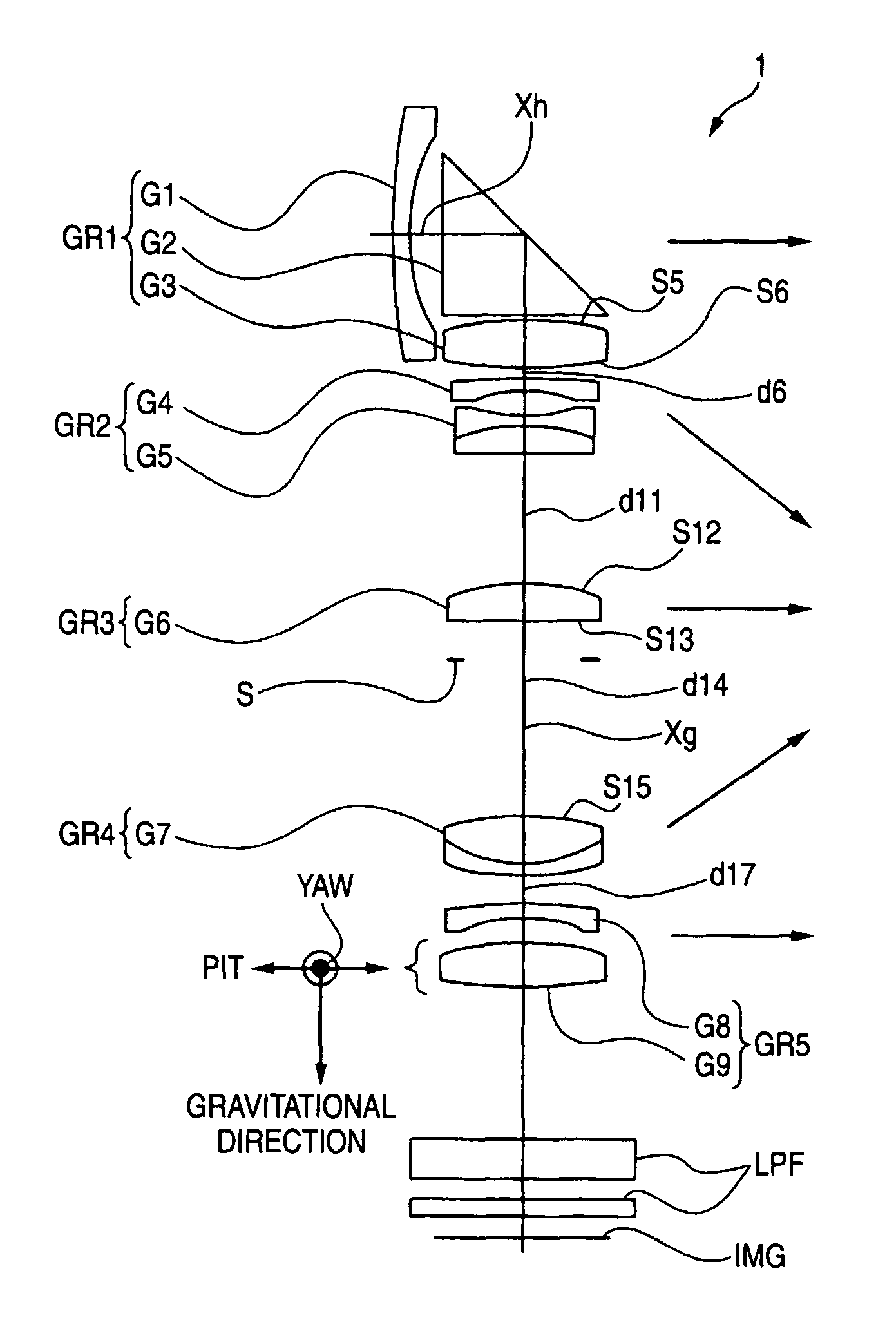
[0037]Best modes for carrying out the imaging lens device and imaging apparatus according to an embodiment of the invention will be described below with reference to the accompanying drawings.

[0038]The imaging lens device according to an embodiment of the invention includes a light path folding optical system having a reflector that folds the optical axis incident perpendicular to the gravitational direction toward the gravitational direction, and an imaging element that converts an image formed by the light path folding optical system into an electrical signal.

[0039]The imaging lens device also includes drive means for moving some of lens groups or one lens (hereinafter referred to as “shake correction lens group”), or the imaging element in the direction perpendicular to the optical axis folded toward the gravitational direction by the reflector (hereinafter referred to as “vertical optical axis”). The imaging lens device is configured such that the shake correction lens group or ...


PUM


Abstract

The invention aims to achieve slim design by employing a light path folding optical system, add a hand-shake correction capability, and lower power consumption. An imaging lens device includes a light path folding optical system having a reflector that folds the optical axis incident perpendicular to the gravitational direction toward the gravitational direction, and an imaging element that converts an image formed by the light path folding optical system into an electrical signal. The imaging lens device also includes drive means that moves some of lens groups or one lens (hereinafter referred to as “shake correction lens group”) in the direction perpendicular to the optical axis folded toward the gravitational direction by the reflector (hereinafter referred to as “vertical optical axis”). The shake correction lens group is moved in the direction perpendicular to the vertical optical axis to move the image in the direction perpendicular to the vertical optical axis.

Description

CROSS REFERENCES TO RELATED APPLICATIONS[0001]The present invention contains subject matter related to Japanese Patent Application JP 2005-217288 filed in the Japanese Patent Office on Jul. 27, 2005, the entire contents of which being incorporated herein by reference.BACKGROUND OF THE INVENTION[0002]1. Field of the Invention[0003]The present invention relates to a novel imaging lens device and imaging apparatus. The invention particularly relates to an imaging lens device that is of compact design and has an anti-vibration capability of correcting image-shake due to unpredictable vibration with less power consumption so that it is suitable for an imaging lens device for digital input / output equipment, such as digital still cameras and digital video camcorders.[0004]2. Description of the Related Art[0005]In recent years, imaging apparatus using a solid-state imaging element, such as digital still cameras, have become commonplace. Among others, in the case of digital still cameras and...

Claims


Application Information

Patent Timeline
Patent Type & Authority Patents(United States)
IPC IPC(8): G03B17/00H04N5/228G02B27/64
CPCG02B13/0035G02B13/0045G02B13/006G02B13/0065G02B13/007G02B13/009G02B15/173G02B27/646G02B15/145113
Inventor KURODA, DAISUKEIWASAWA, YOSHITOKANAI, MAKOTO
Owner SONY CORP
Why Eureka
Try Eureka