Bushing and a method for producing the same

a technology of bushings and flanges, applied in the field of bushings, can solve the problems of high cost, complicated manufacturing process, and metal bushings that are not known, and achieve the effect of improving the service life and reducing the cost of manufacturing

Inactive Publication Date: 2010-10-12
ABB POWER GRIDS SWITZERLAND AG +1
View PDF6 Cites 15 Cited by
  • Summary
  • Abstract
  • Description
  • Claims
  • Application Information

AI Technical Summary

Benefits of technology

[0006]A method of producing a bushing is disclosed having a rotationally symmetrical core surrounding an axial duct for accommodating a conductor, a grading insulation surrounding the axial duct, a plurality of conductor layers which are electrically insulated from each other, a shell having an insulating matrix material with a test contact connected to an outermost of the conductor layers of the grading insulation, a flange in one piece with the shell formed at least in part of the insulating matrix material, with at least one metal insert at least partially embedded in the insulating matrix material adjacent to through holes such that the at least one metal insert forms at least part of a surface of the flange surrounding the through holes on a second side of the flange opposite a mounting side of the bushing, and at least one electrically conductive connection element which connects a grounding contact with the at least one metal insert, the method comprising: placing at least components of the grading insulation, the test contact, the at least one metal insert and the at least one connection element in a mould; filling the mould with the insulating matrix material in a liquid form; allowing the insulating matrix material to harden; and removing the bushing from the mould.

Problems solved by technology

Known bushings can include flanges made of metal, in particular of aluminium and can be expensive.
In particular, the manufacturing process can be rather complicated.

Method used


Image

  • Bushing and a method for producing the same
  • Bushing and a method for producing the same
  • Bushing and a method for producing the same

Examples


Embodiment Construction

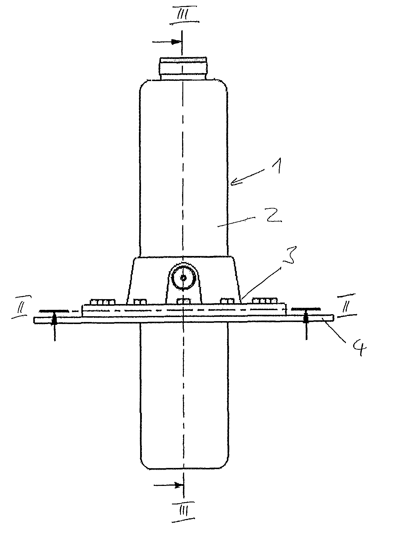
[0012]An exemplary bushing according to the disclosure can be robust and can be reliably fixed to a wall while also establishing a desired electrically conductive connection of a grounding contact with the bushing.

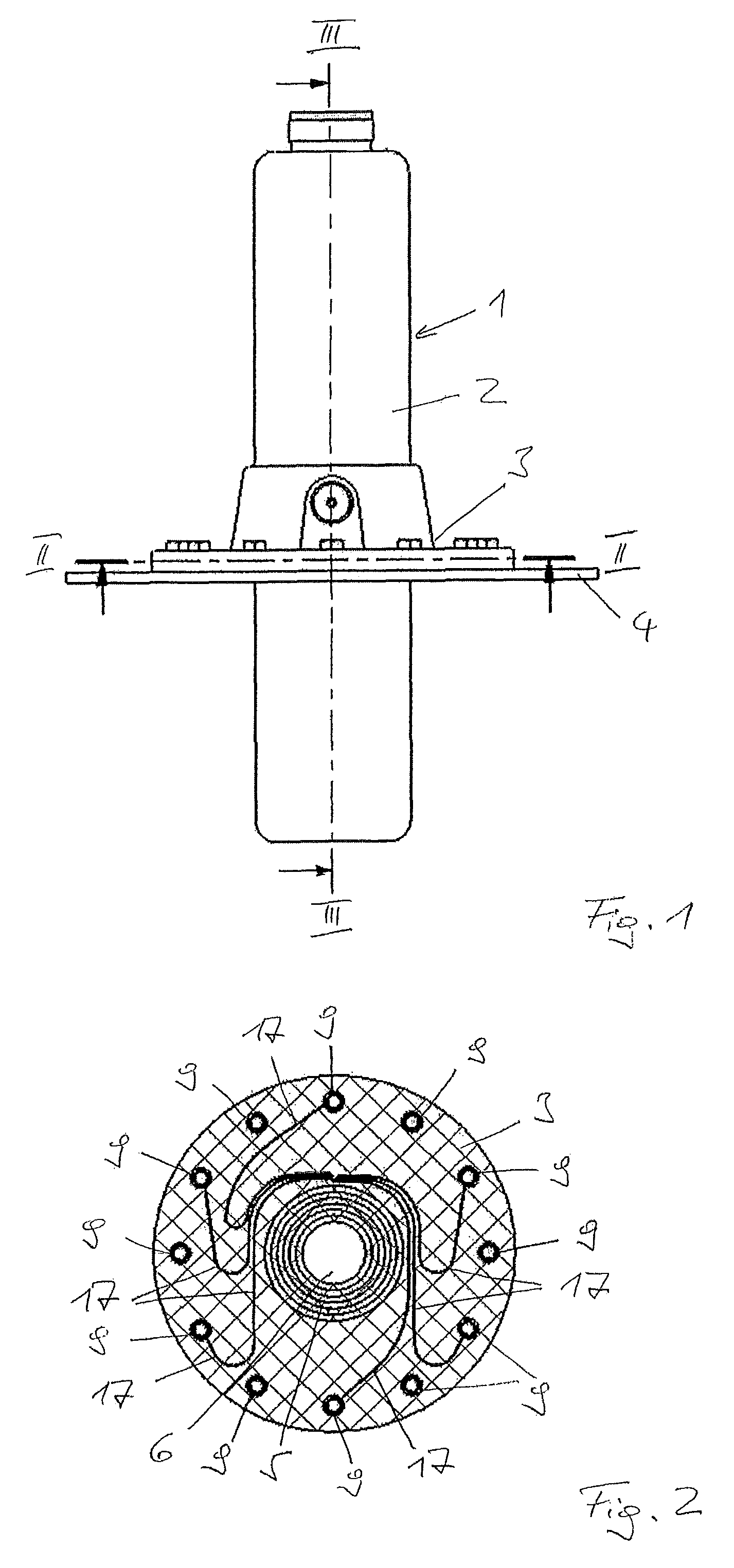
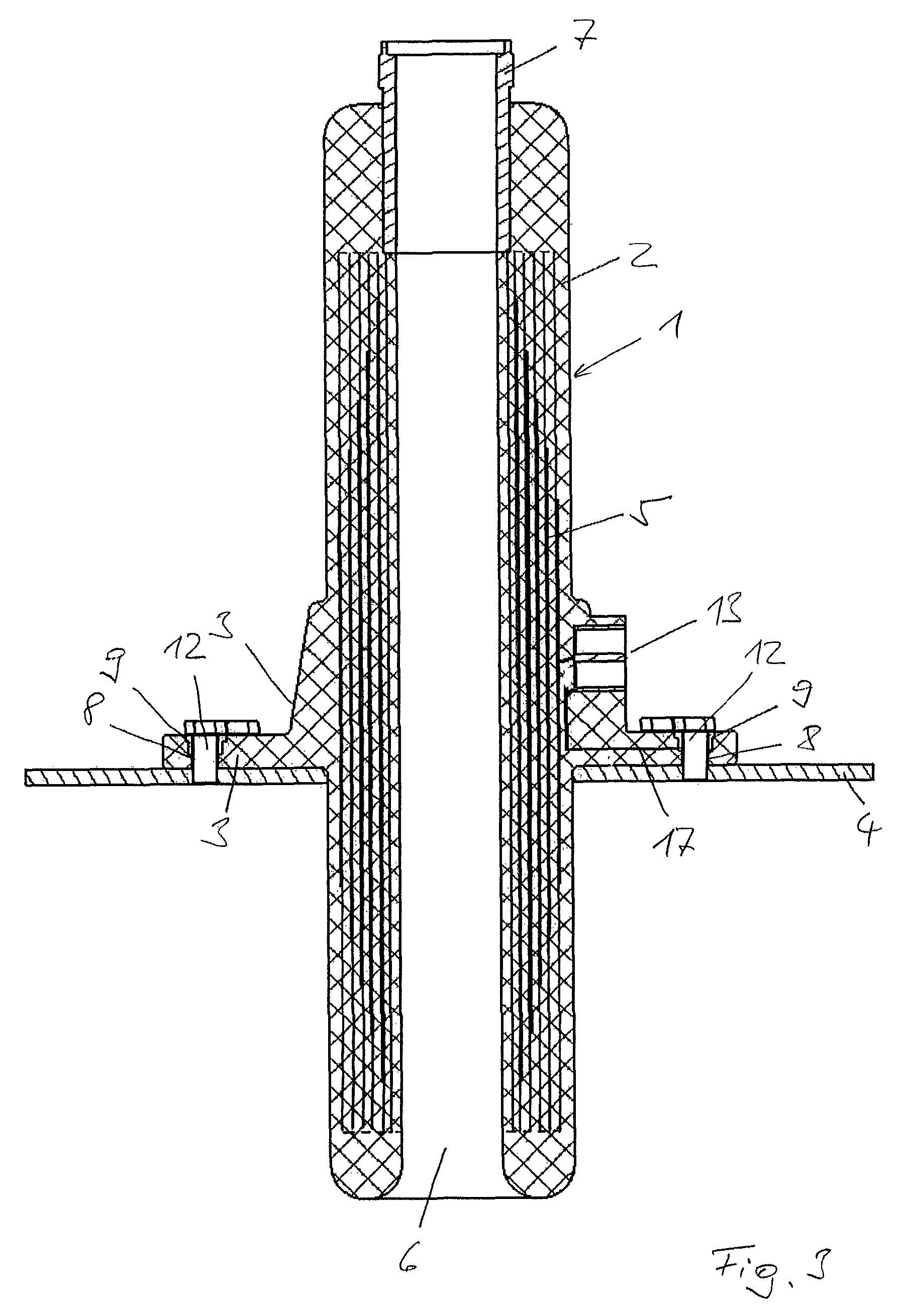
[0013]A particularly simple and cost-efficient way of producing a bushing is also disclosed where, after positioning elements of a grading insulation and other components in a mould, the bushing, including the flange, can be completed in substantially one shot by filling of the mould with insulating matrix material in liquid form.

[0014]According to the disclosure, an exemplary flange is in one piece with the core, comprising the same insulating matrix material. No machining is required, and production costs can be considerably reduced. However, the surface of a plastic flange can be too soft to withstand high mechanical loads exerted on it by bolts used to mount the bushing to, e.g., any kind of plane, a housing or a wall. Also, while the metal flange of known generic bush...


PUM


Abstract

A bushing is disclosed with a duct for accommodating a conductor which is surrounded by an electrical field grading insulation. The bushing includes a core with a shell encapsulating the grading insulation and a flange surrounding the shell and carrying through holes distributed over its circumference for allowing the bushing to be attached to a wall. The shell and the flange can be in one piece and include an insulating matrix material. The through holes can be surrounded by metal inserts each forming an annular surface flush with a surface of the flange. A test tap can include a contact pin which is electrically conductively connected to an outermost layer of the grading insulation and surrounded by a contact ring connected to every second metal insert by connection wires for grounding the contact pin via the contact ring when the test tap is not in use and covered. The core can be produced by filling a mold with the liquid matrix material after components of the grading insulation and other parts have been fixed in the liquid matrix material.

Description

RELATED APPLICATION[0001]This application claims priority as a continuation application under 35 U.S.C. §120 to PCT / CH2006 / 000726 filed as an International Application on Dec. 20, 2006 designating the U.S., the entire content of which is hereby incorporated by reference in its entirety.FIELD[0002]The disclosure concerns a bushing and a method for producing such bushing.BACKGROUND INFORMATION[0003]Bushings are known, for example, as electrical condenser bushings used in medium and high voltage electrical installations for leading a conductor through a grounded barrier (e.g., a metal wall of a transformer, tank or substation housing or similar).[0004]Known bushings can include flanges made of metal, in particular of aluminium and can be expensive. In particular, the manufacturing process can be rather complicated. First, a core comprising an electrical field grading insulation and a test tap connection point is produced, e.g., by moulding and finished by machining. The expensive metal...

Claims


Application Information

Patent Timeline
Patent Type & Authority Patents(United States)
IPC IPC(8): H02G3/18
CPCH01B17/265H01B17/005Y10T16/063Y10T16/05H01B17/28
Inventor ROCKS, JENSTILLIETTE, VINCENTCHALIKIA, GERDHEDLUND, ROGERGABRIEL, MICHAEL
Owner ABB POWER GRIDS SWITZERLAND AG
Why Eureka
Try Eureka