Antennas for deep induction array tools with increased sensitivities

an array tool and induction array technology, applied in the field can solve the problems of more strong influence of tools, complicated resistivity logging and interpretation, and increased sensitivities of induction array tools

Active Publication Date: 2010-10-12
SCHLUMBERGER TECH CORP
View PDF11 Cites 19 Cited by
  • Summary
  • Abstract
  • Description
  • Claims
  • Application Information

AI Technical Summary

Problems solved by technology

In addition to borehole fluid invasion, formation anisotropy can also complicate resistivity logging and interpretation.
Further, formation analysis is also problematic for thin or highly laminated beds due to a lack of sensitivity of logging tools.
While the TMD tools (including tri-axial tools) are capable of providing additional information about the formation resistivity, these tools are more strongly affected by the borehole for transmitter-receiver spacings less than a few meters, particularly in high contrast situations, when the mud in the borehole is more conductive than the formation.
Further, at least partially due to the lack of sensitivity of currently available wireline and LWD EM induction array tools, geologists and petrophysicists historically have found it necessary to visually analyze core samples extracted from zones of interest to assess complex or thinly laminated reservoirs and aid in the discovery of hydrocarbons.
Because core samples can be difficult and / or costly to obtain, EM induction array tools with increased sensitivities are needed for the tensor conductivity volumetric measurements required to evaluate reservoir geometry and water / hydrocarbon boundary movement.

Method used


Image

  • Antennas for deep induction array tools with increased sensitivities
  • Antennas for deep induction array tools with increased sensitivities
  • Antennas for deep induction array tools with increased sensitivities

Examples


Embodiment Construction

[0038]The improved antenna designs disclosed herein are suited for use in modified downhole induction logging tools. Currently available deep induction tools are disclosed, for example, in U.S. Pat. Nos. 7,093,672, 7,046,009 and 7,027,922. For example, the sensitive antennas disclosed herein can be places along the tool string with shallow, medium and deep spacings of around 10, 30, and 100 meters. Ultra deep spacings could be in the range of 200 meters or more. Sets or arrays of orthogonal coils yield a 3×3 conductivity matrix measurement of the reservoir from which is inverted to the formation resistivities and which can be used to generate a three dimensional resistivity image of the formation.

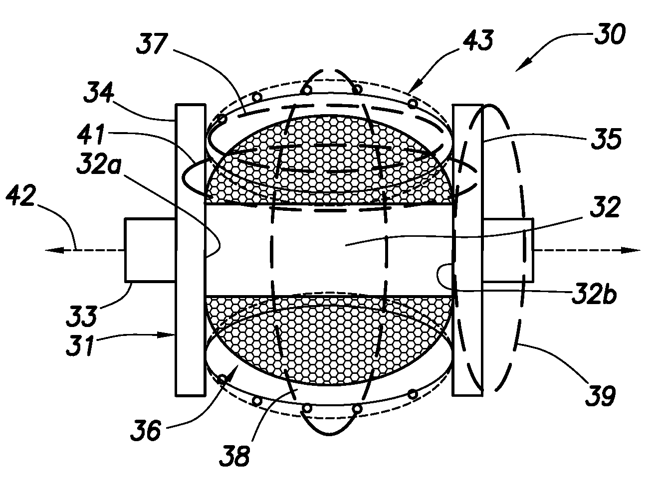
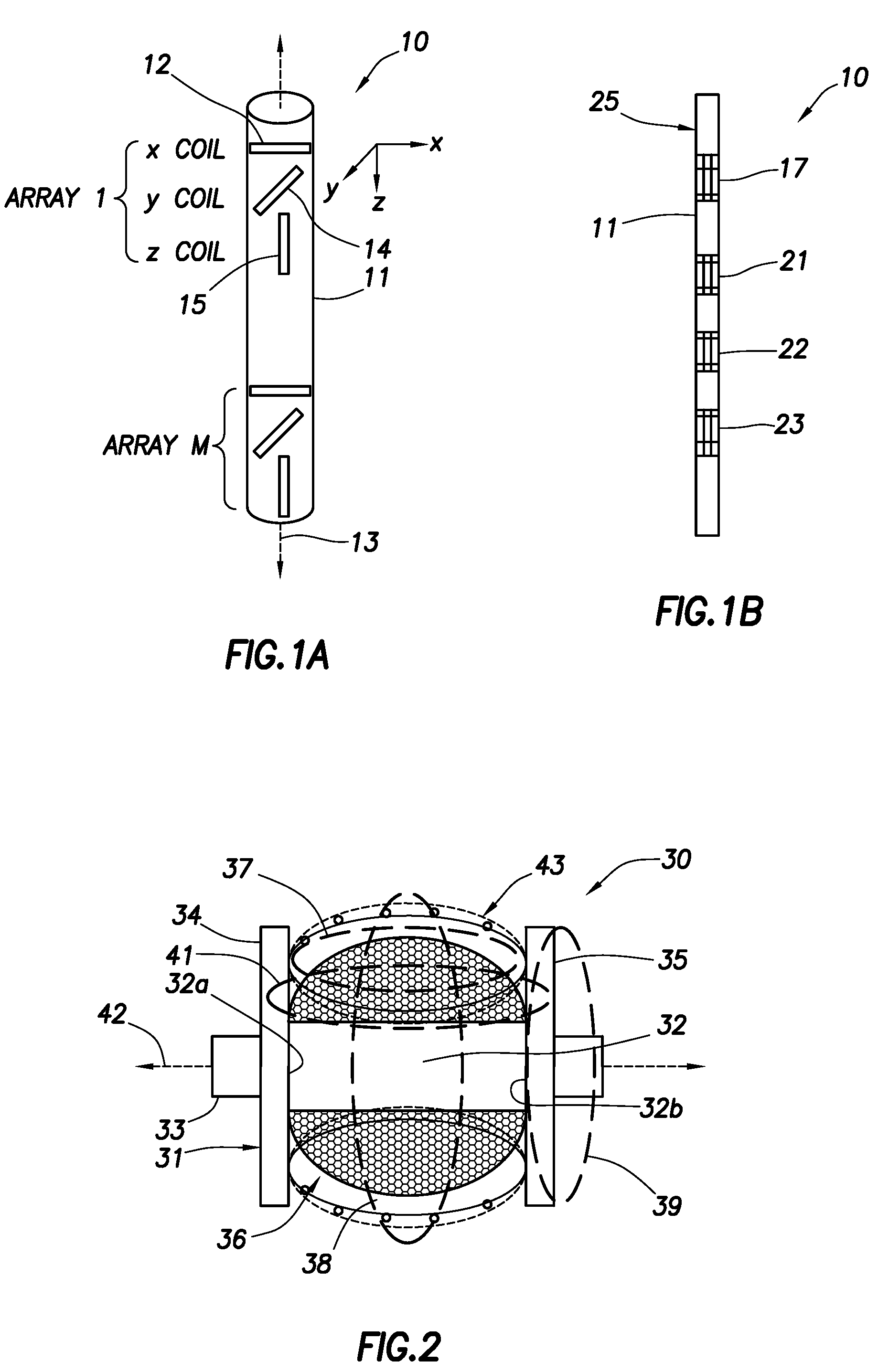
[0039]Therefore, without going into exhaustive detail about how logging while drilling (“LWD”) induction tools are designed, FIGS. 1A and 1B illustrate the type of induction logging tools that are candidates for the disclosed improved antennas. In FIG. 1A, a partial view of a tool 10 is dis...


PUM

PropertyMeasurementUnit
aspect ratioaaaaaaaaaa

Abstract

Improved receiver antennas are disclosed for long offset tensor induction army logging tools. The disclosed antennas include a bobbin which accommodates a ferromagnetic core. The outer surface of the bobbin is wrapped around a binding so that winding is thicker or includes more turns towards a center of the bobbin and is thinner or includes less turns towards the outer ends of the bobbin. The result is that the primary winding with a curved or parabolic profile that enhances the effective magnetic permeability and magnetic moment of the antenna. A secondary winding may also be utilized for flux feedback compensation. The elimination of winding turns towards the ends of the magnetic coil result in reduced DC resistance and the reduction in parasitic capacitance of the antennas. The disclosed antennas may be used in x-y-z receiver arrays.

Description

BACKGROUND[0001]1. Technical Field[0002]Induction array tools and related techniques for formation resistivity logging are disclosed. More specifically, antennas for induction array tools for long transmitter-receiver off-sets, with increased sensitivities and related methods of use in resistivity measurements and formation or reservoir geometry are disclosed. Still more specifically, a deep triaxial resistivity tensor measurement tool is disclosed which assists in understanding geometries of hydrocarbon bearing formations. The disclosed tool can be used during the production phase of a reservoir to assist in understanding of induced or natural water fronts.[0003]2. Description of the Related Art[0004]Electromagnetic (EM) induction array toots are used in the oil and gas industry to determine the resistivity of earth formations surrounding a borehole. Because hydrocarbons have a higher resistivity than water or salt water, resistivity measurements are a primary means for locating or...

Claims


Application Information

Patent Timeline
Patent Type & Authority Patents(United States)
IPC IPC(8): G01V3/18H01F27/28
CPCG01V3/28H01Q7/08H01Q1/04
Inventor MARTINEZ, ISMAELHOMAN, DEAN M.VILLEGAS, LAURENTHAZEN, GARY A.
Owner SCHLUMBERGER TECH CORP
Why Eureka
Try Eureka