Flash memory and method of dynamically loading firmware operation module in optical drive

a firmware operation and flash memory technology, applied in the field of flash memory and dynamic loading firmware operation modules in optical drives, can solve the problem of limited space for adding a code for debugging optical drives, and achieve the effect of efficient operation

Inactive Publication Date: 2010-10-12
Y P LEE MOCK & PARTNERS +1
View PDF14 Cites 22 Cited by
  • Summary
  • Abstract
  • Description
  • Claims
  • Application Information

AI Technical Summary

Benefits of technology

[0010]An aspect of the invention also provides a method of dynamically loading a firmware operation module to an optical drive, by which a firmware having various functions can be installed in a small area of the flash memory and efficiently perform operations for debugging and controlling the optical drive in the small area of the flash memory.

Problems solved by technology

Firmware code increases when functions of the firmware area increased; therefore, there is limited space for adding a code for debugging an optical drive and a code for controlling the optical drive to the optical drive.

Method used


Image

  • Flash memory and method of dynamically loading firmware operation module in optical drive
  • Flash memory and method of dynamically loading firmware operation module in optical drive
  • Flash memory and method of dynamically loading firmware operation module in optical drive

Examples


Embodiment Construction

[0021]Reference will now be made in detail to the embodiments of the present invention, examples of which are illustrated in the accompanying drawings, wherein like reference numerals refer to the like elements throughout. The embodiments are described below to explain the present invention by referring to the figures.

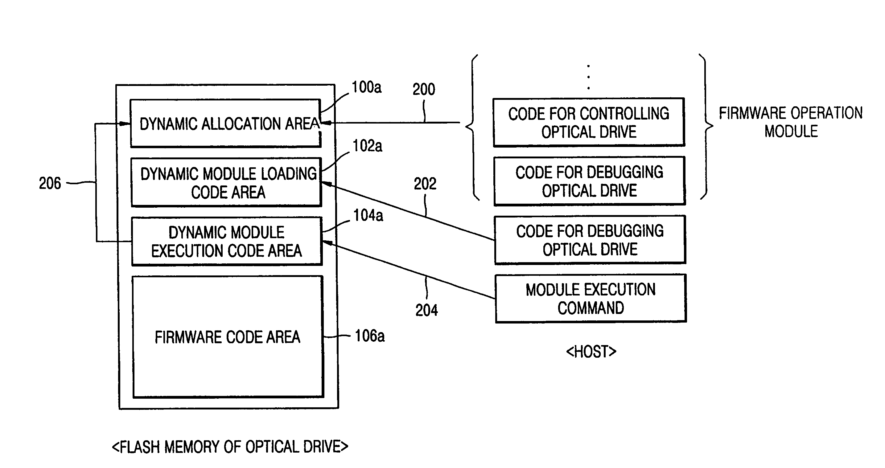
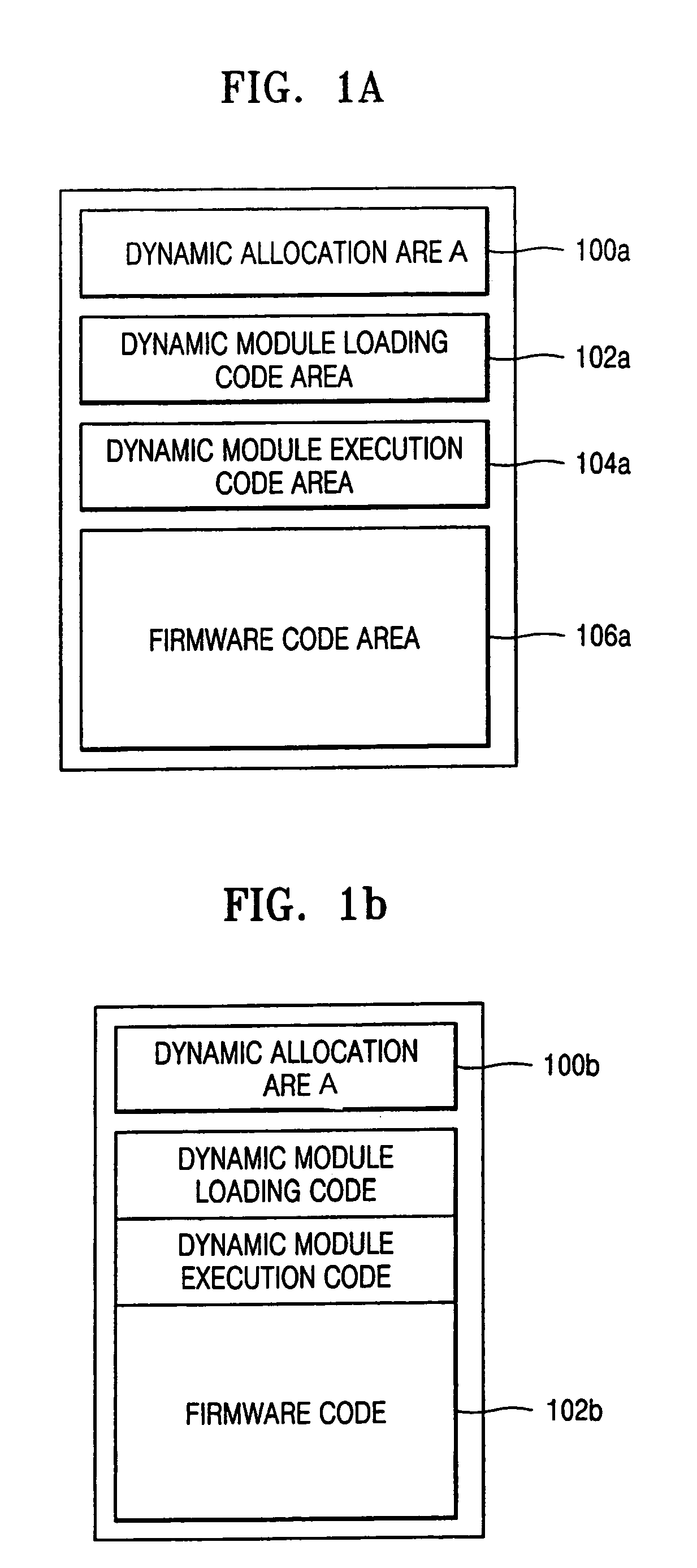
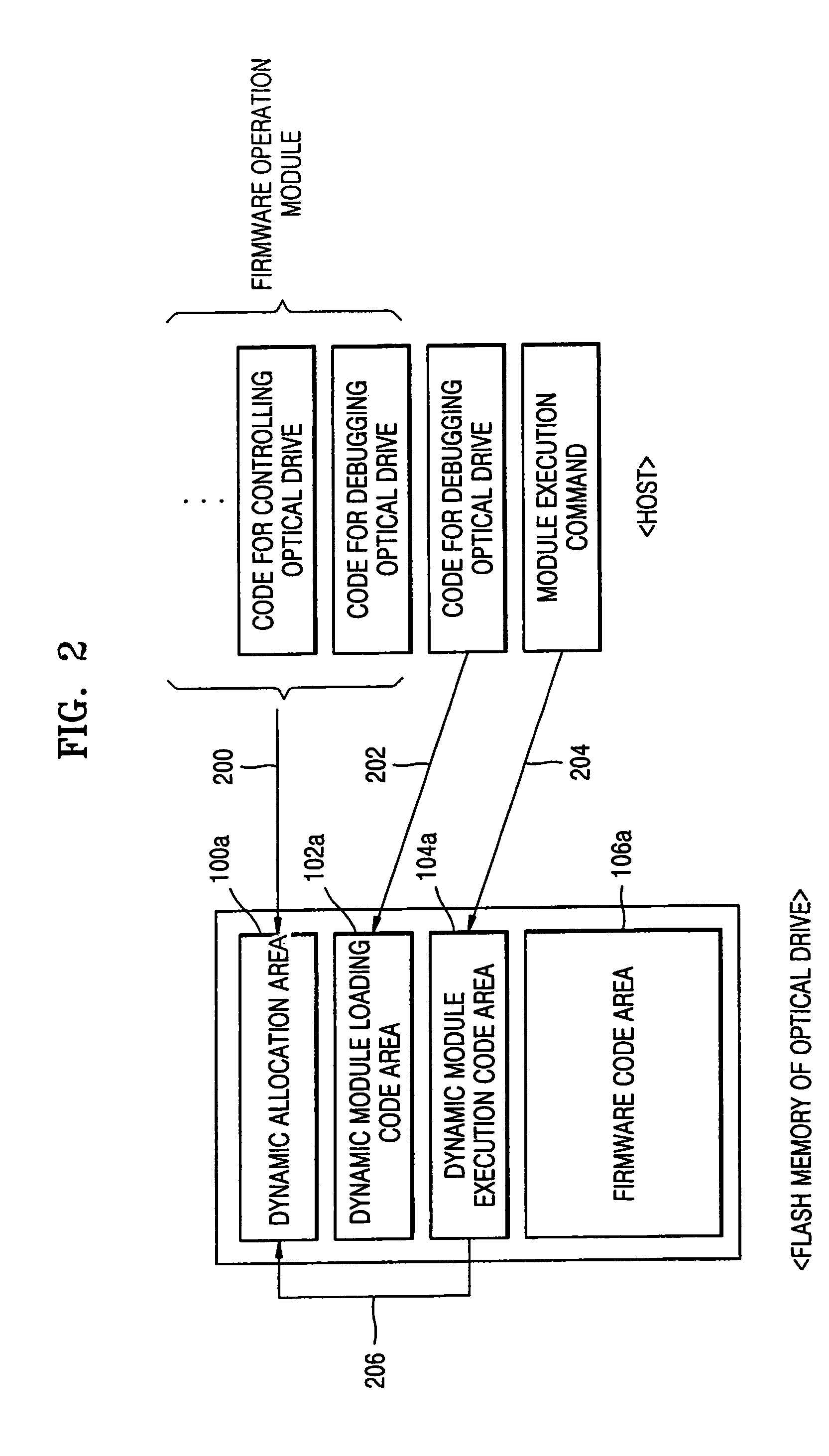
[0022]A flash memory of FIG. 1A includes at least a dynamic allocation area 100a, a dynamic module loading code area 102a, a dynamic module execution code area 104a, and a firmware code area 106a. For example, the dynamic module may be stored separately in the flash memory and optionally loaded at a run time.

[0023]The dynamic allocation area 100a is used to store, execute, and delete a firmware operation module (e.g., a code for debugging an optical drive and a code for controlling the optical drive) received from a host. To perform a firmware operation, an area of a fixed address is allocated to some area of the flash memory. For example, the firmware operation module...


PUM

PropertyMeasurementUnit
areaaaaaaaaaaa
areasaaaaaaaaaa
storage areaaaaaaaaaaa

Abstract

A flash memory in which a code for debugging an optical drive and a code for controlling the optical drive are downloaded when required, the functions of the downloaded code are subsequently executed, and the executed code is then deleted. The flash memory includes a first area where a firmware operation module that is received from an external source is executed and deleted; and a second area allocated to store a code for loading the firmware operation module that is stored in the first area, a code for executing the firmware operation module that is stored in the first area, and a firmware code.

Description

CROSS-REFERENCE TO RELATED APPLICATION[0001]This application claims the benefit of Korean Patent Application No. 2004-12543, filed on Feb. 25, 2004, in the Korean Intellectual Property Office, the disclosure of which is incorporated herein in its entirety by reference.BACKGROUND OF THE INVENTION[0002]1. Field of the Invention[0003]The present invention relates to a flash memory in which a code for debugging an optical drive and a code for controlling the optical drive are downloaded when required, subsequently executed, and then deleted, and a method of dynamically loading a firmware operation module to an optical drive.[0004]2. Description of the Related Art[0005]A flash memory of an optical drive stores a firmware code for driving the optical drive, a code for debugging the optical drive, and a code for controlling the optical drive.[0006]Firmware is generally a mediator that connects the software and the hardware. For example, when several hardware are installed on a main board, ...

Claims


Application Information

Patent Timeline
Patent Type & Authority Patents(United States)
IPC IPC(8): G06F12/00G06F11/00G06F15/177G06F9/00G06F13/28G06F13/00G06F9/44H03M1/12G06F9/445G11B7/00G11B19/02G11B20/04
CPCG06F8/60G06F8/665G06F9/44594G06F8/654G11B20/04
Inventor LEE, KI-JU
Owner Y P LEE MOCK & PARTNERS
Why Eureka
Try Eureka