
Auto-safety shut-off for energy based devices

a technology of energy-based devices and shut-offs, which is applied in the field of auto-safety shut-off for energy-based devices, can solve the problems of small force required by devices to pass through tissue, and the risk of additional tissue penetration

Active Publication Date: 2010-10-19
CILAG GMBH INT
View PDF12 Cites 40 Cited by
  • Summary
  • Abstract
  • Description
  • Claims
  • Application Information

AI Technical Summary

Benefits of technology

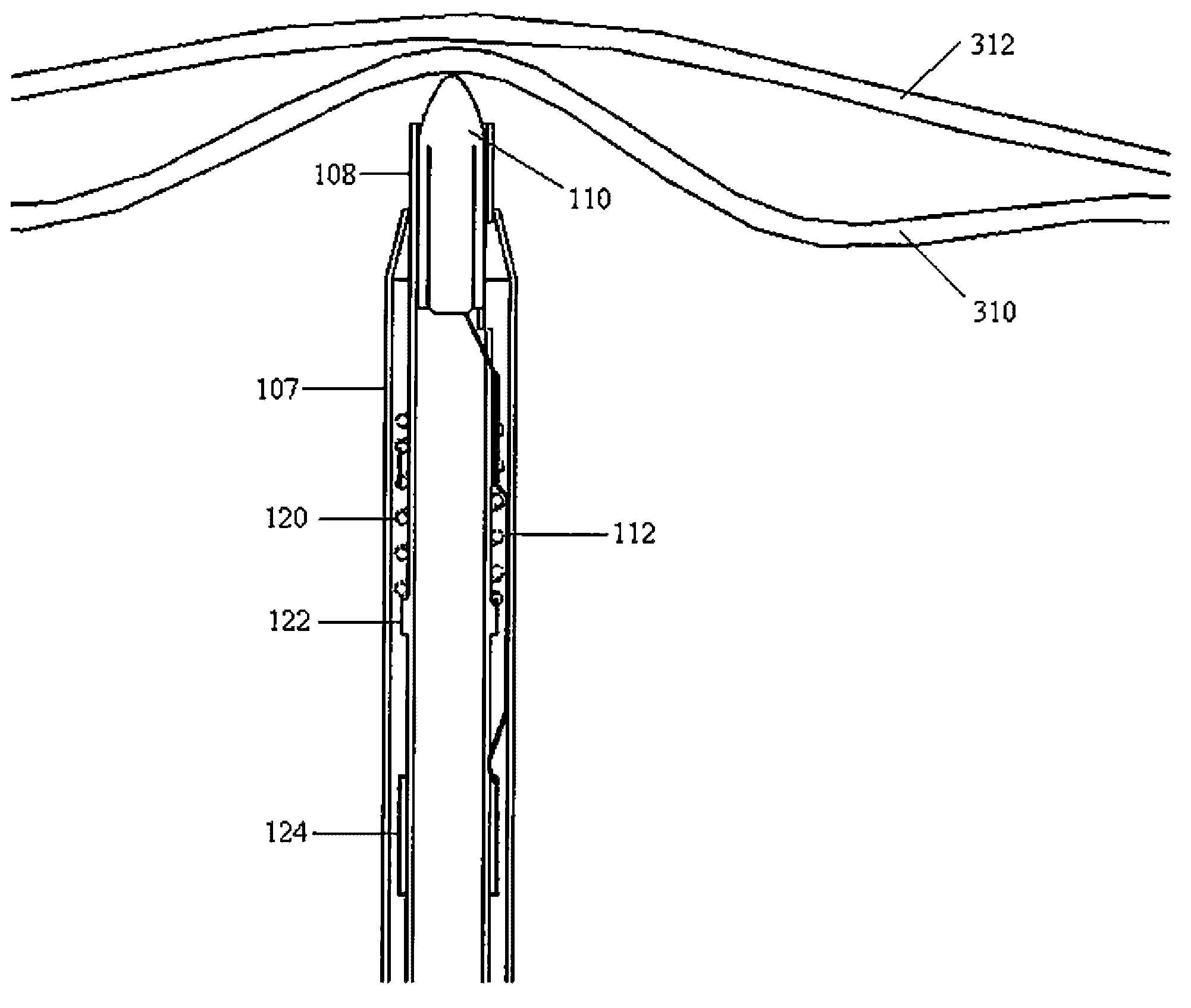
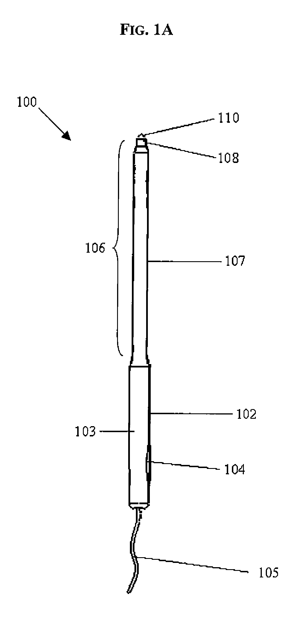
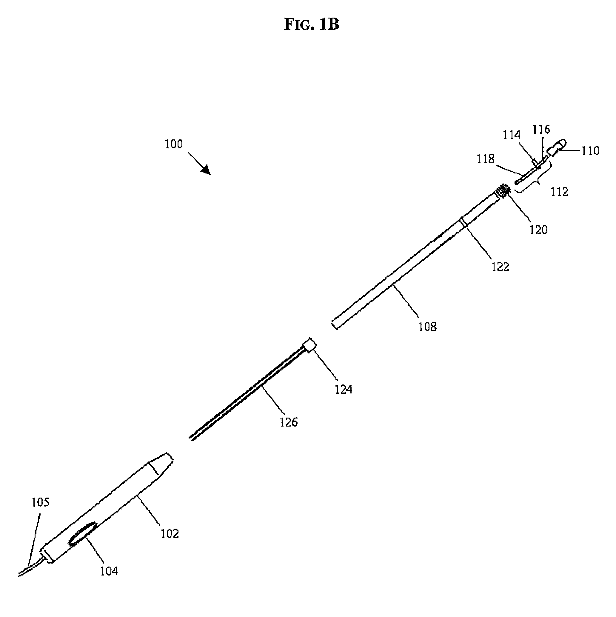
The present invention provides devices and methods for surgically treating tissue, such as by cutting and / or coagulating tissue. The device includes a conductive tip that can be moved between a first and second position. In the first position, the conductive tip is disconnected from a conductive contact which is adapted to communicate with an energy source. In the second position, the conductive tip is in contact with the conductive contact such that energy can be delivered from the energy source through the conductive contact to the conductive tip. The conductive tip can have a variety of shapes and sizes, but in one embodiment, it is a blunt tip. The conductive connector can include a collar, a first extension arm, and a second extension arm. The device can also include a biasing element effective to bias the conductive tip to the first position. The method involves contacting tissue with the conductive tip, allowing it to move to an electrically activated position where energy is delivered to treat the tissue. The conductive tip then moves to an electrically deactivated position after it passes through or loses contact with the tissue.

Problems solved by technology

These devices only required small amounts of force to pass through tissue, while only affecting the tissue directly near the portion of the device receiving the energy.
While the use of energy for such devices is increasingly popular, it is not without its disadvantages.
Due to the low force of penetration needed to pass through tissue, there is the risk of penetrating additional tissue that is intended to be left unharmed during the procedure.
This could result in damage and / or destruction of sections of secondary tissue or organs.

Method used


Image

  • Auto-safety shut-off for energy based devices
  • Auto-safety shut-off for energy based devices
  • Auto-safety shut-off for energy based devices

Examples


Embodiment Construction

[0019]Certain exemplary embodiments will now be described to provide an overall understanding of the principles of the structure, function, manufacture, and use of the devices and methods disclosed herein. One or more examples of these embodiments are illustrated in the accompanying drawings. Those skilled in the art will understand that the devices and methods specifically described herein and illustrated in the accompanying drawings are non-limiting exemplary embodiments and that the scope of the present invention is defined solely by the claims. The features illustrated or described in connection with one exemplary embodiment may be combined with the features of other embodiments. Such modifications and variations are intended to be included within the scope of the present invention.

[0020]Various exemplary methods and devices are provided for cutting and / or coagulating tissue. In particular, methods and devices are provided which can include an auto-shutoff feature which terminat...


PUM


Abstract

Various methods and devices are provided for surgically treating tissue. In one embodiment, the device can include a shaft having proximal and distal ends and a conductive tip disposed within the distal end of the shaft and movable between a first and second position. In the first position, the conductive tip is disconnected from a conductive contact which is adapted to communicate with an energy source. In the second position, the conductive tip is in contact with the conductive contact such that energy can be delivered from an energy source through the conductive contact to the conductive tip. The conductive tip can have a variety of shapes and sizes, but in one exemplary embodiment, the conductive tip is a blunt tip. The conductive contact can include at least one lead extending therefrom and adapted to communicate with an energy source.

Description

BACKGROUND OF THE INVENTION[0001]A wide variety of devices are used during surgical procedures for treating tissue, such as for cutting and / or coagulation. Electrosurgical instruments have been developed that utilize energy for performing these functions. For example, instruments utilizing radio frequency (RF) energy provide current and / or heat that can be used for cutting and coagulating tissues. These devices only required small amounts of force to pass through tissue, while only affecting the tissue directly near the portion of the device receiving the energy.[0002]While the use of energy for such devices is increasingly popular, it is not without its disadvantages. Due to the low force of penetration needed to pass through tissue, there is the risk of penetrating additional tissue that is intended to be left unharmed during the procedure. This could result in damage and / or destruction of sections of secondary tissue or organs.[0003]Accordingly, there is a need for improved devic...

Claims


Application Information

Patent Timeline
Patent Type & Authority Patents(United States)
IPC IPC(8): A61B18/12
CPCA61B18/148A61B17/3496A61B2019/481A61B2018/00601A61B2018/124A61B2018/00589A61B2090/08021
Inventor ORTIZ, MARK S.
Owner CILAG GMBH INT
Learn More