Air vehicle wing pivot

a technology for air vehicles and wing pivots, which is applied in the direction of wings, weapons, transportation and packaging, etc., can solve the problems of reducing the aerodynamic efficiency of the wing, reducing the range and mission effectiveness, and reducing the wing span

Inactive Publication Date: 2010-10-19
THE BOEING CO
View PDF3 Cites 35 Cited by
  • Summary
  • Abstract
  • Description
  • Claims
  • Application Information

AI Technical Summary

Problems solved by technology

Reducing the wing span reduces the aerodynamic efficiency of the wing, with impacts of decreased range and mission effectiveness.

Method used


Image

  • Air vehicle wing pivot
  • Air vehicle wing pivot
  • Air vehicle wing pivot

Examples


Embodiment Construction

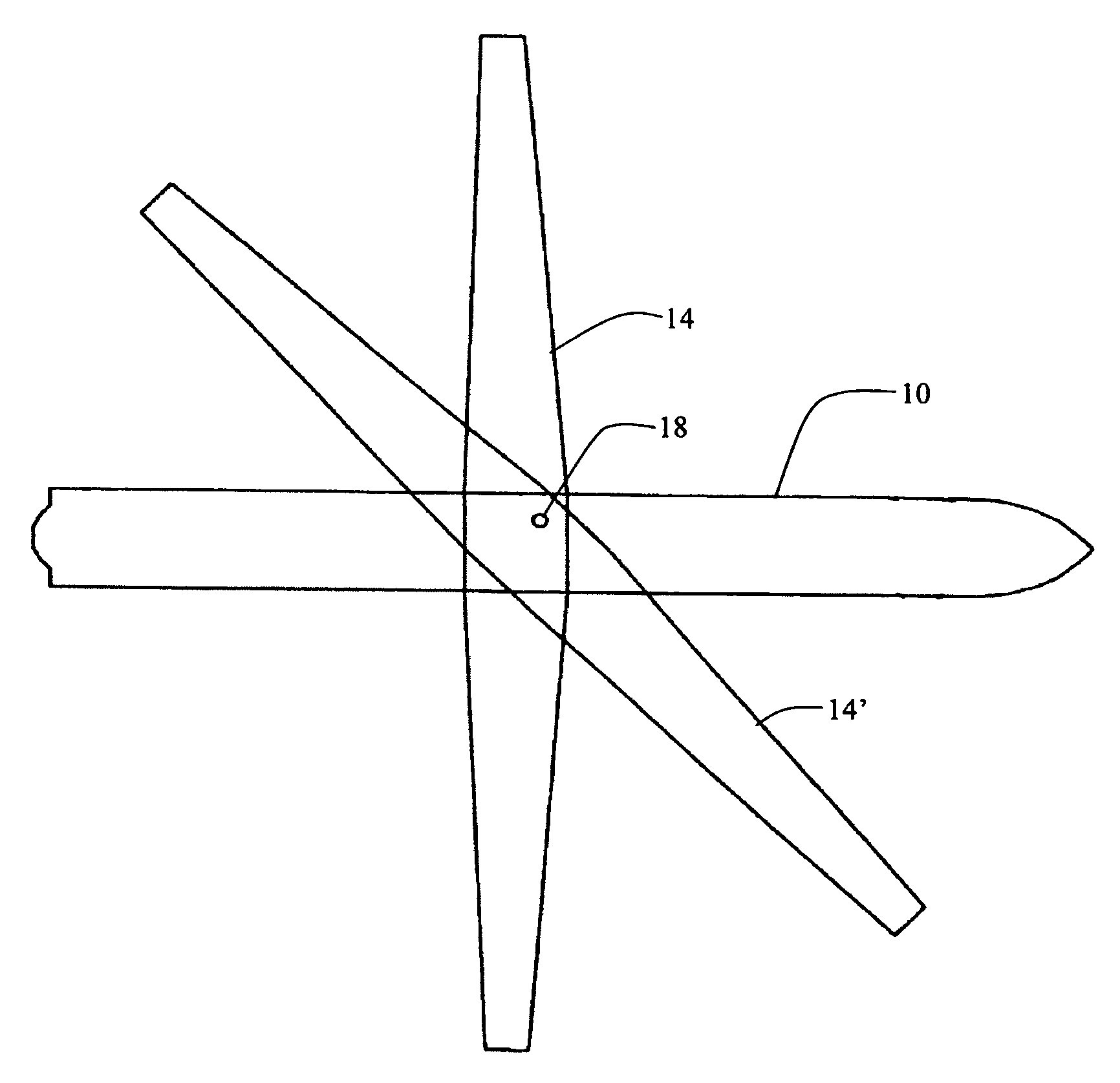
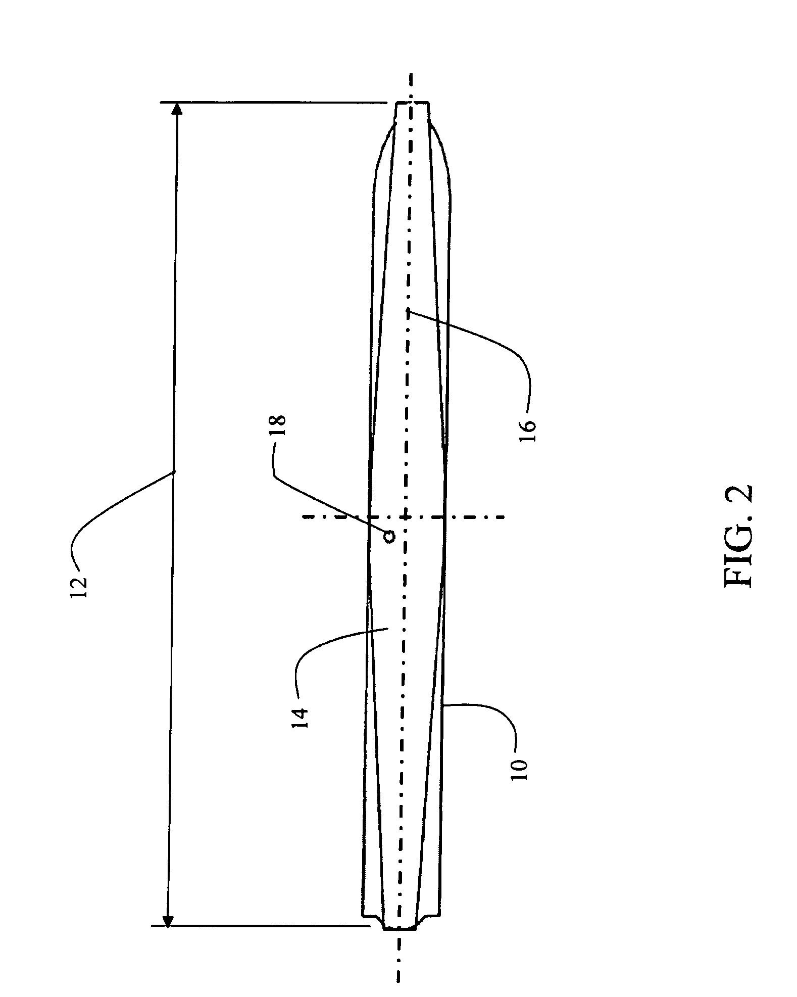
[0025]An exemplary embodiment is shown in FIGS. 2, 3 and 4. The air vehicle fuselage 10 has a length 12 determined by the internal systems and propulsion requirements. This length becomes the determining dimensional benchmark for the overall system and is equal to the maximum length of a wing 14 which can be accommodated in a folded or stowed position for storage or launch from a container of minimum length.

[0026]As shown in FIG. 2, the wing in the stowed position is longitudinally aligned with the fuselage centerline 16. FIG. 3 shows the air vehicle with the wing in the deployed position substantially perpendicular to the fuselage. As shown for the embodiment in the drawings, the wing is symmetrical with respect to the fuselage thereby providing simplicity in aerodynamic control.

[0027]As shown in detail in FIG. 4, a pivot 18 for the wing is located at a point off-center from the centerline of the fuselage and forward of a chord center 20. Location of the pivot at a predetermined po...


PUM


Abstract

A stowable wing structure incorporates a wing having a span equal to a fuselage length and movable from a stowed position longitudinally aligned with the fuselage to a deployed position perpendicular to the fuselage. A pivot offset laterally from a centerline of the fuselage and aft from a symmetry point on the centerline with a corresponding offset forward toward the leading edge from a chord centerpoint on the wing allows rotation of the wing from the stowed position to the deployed position with the rotation resulting in an aft position of the chord center point relative to the fuselage symmetry point.

Description

STATEMENT REGARDING FEDERALLY SPONSORED RESEARCH OR DEVELOPMENT[0001]This invention was developed partially with government funding pursuant to USAF contract no. F08630-03-C-0049. The United States government has certain rights in the invention disclosed herein.BACKGROUND[0002]1. Field[0003]Embodiments of the disclosure relate generally to the field of compact storage of air-launched weapons systems and more particularly to a geometric location of a wing pivot for an air vehicle wing stored aligned with the vehicle fuselage and deployed to a operational position perpendicular to the fuselage with an aft shift of the aerodynamic center of the wing while remaining symmetrical in the deployed position.[0004]2. Description of the Related Art[0005]Cruise missiles and other air-launched or tube-launched air vehicles or reconnaissance systems must be stored in and launched from volumetrically constrained housings. A length-limited cruise missile may have a single piece wing that is stowed ...

Claims


Application Information

Patent Timeline
Patent Type & Authority Patents(United States)
IPC IPC(8): F42B10/14
CPCB64C3/56B64C39/024F42B10/14F42B15/105B64C2201/102Y02T50/145Y02T50/10B64U30/12
Inventor FINK, LAWRENCE E.
Owner THE BOEING CO
Why Eureka
Try Eureka