Portable electrical distribution enclosure

a technology for electrical equipment and enclosures, which is applied in the direction of electrical apparatus casings/cabinets/drawers, inorganic insulation, coupling device connections, etc., can solve the problems of gas out and fire, and achieve the effects of high impact, high density, and convenient portability

Inactive Publication Date: 2010-10-19
NEUMANN BARRY +1
View PDF15 Cites 30 Cited by
  • Summary
  • Abstract
  • Description
  • Claims
  • Application Information

AI Technical Summary

Benefits of technology

[0005]The portable electrical distribution enclosure has a chassis made of anodize aluminum. The chassis has a bottom panel and two side panels. The two side panels extend parallel to each other and at right angles from the bottom panel making the chassis rectangular. The enclosure further includes high density polyethylene front and rear panels. The front and rear panels receive the chassis and securely connect to the bottom panel and each of the two side panels of the chassis. The front panel and the rear panel each have a pair of legs extending below the bottom panel. The front and rear legs insure that the chassis is off the ground to permit air to flow under the chassis and into vents to cool the chassis during use of the portable electrical distribution enclosure.
[0006]There is also a high density polyethylene (HDPE) top with at least one handle. The handle permits the enclosure to be readily portable because of the lightweight material. The high density polyethylene top securely connects to the two side panels of the chassis and to the front and rear panels. The high density polyethylene panels and top can withstand high impacts and any collateral damage from surrounding environment, weather, or marine applications. Thus, the high density polyethylene panels and top protect the inner electrical components mounted in the chassis, as well as any protruding receptacles and outlets.

Problems solved by technology

Sometimes, the temporary power distribution must be carried through or used in confined spaces that do not afford much room.
Prior designs were made from steel or other conductive material that created an unsafe environment during shortages or malfunctions.
Even those made from rubber tended to generate heat from electrical currents that caused problems such gas out and fires.

Method used


Image

  • Portable electrical distribution enclosure
  • Portable electrical distribution enclosure
  • Portable electrical distribution enclosure

Examples


Embodiment Construction

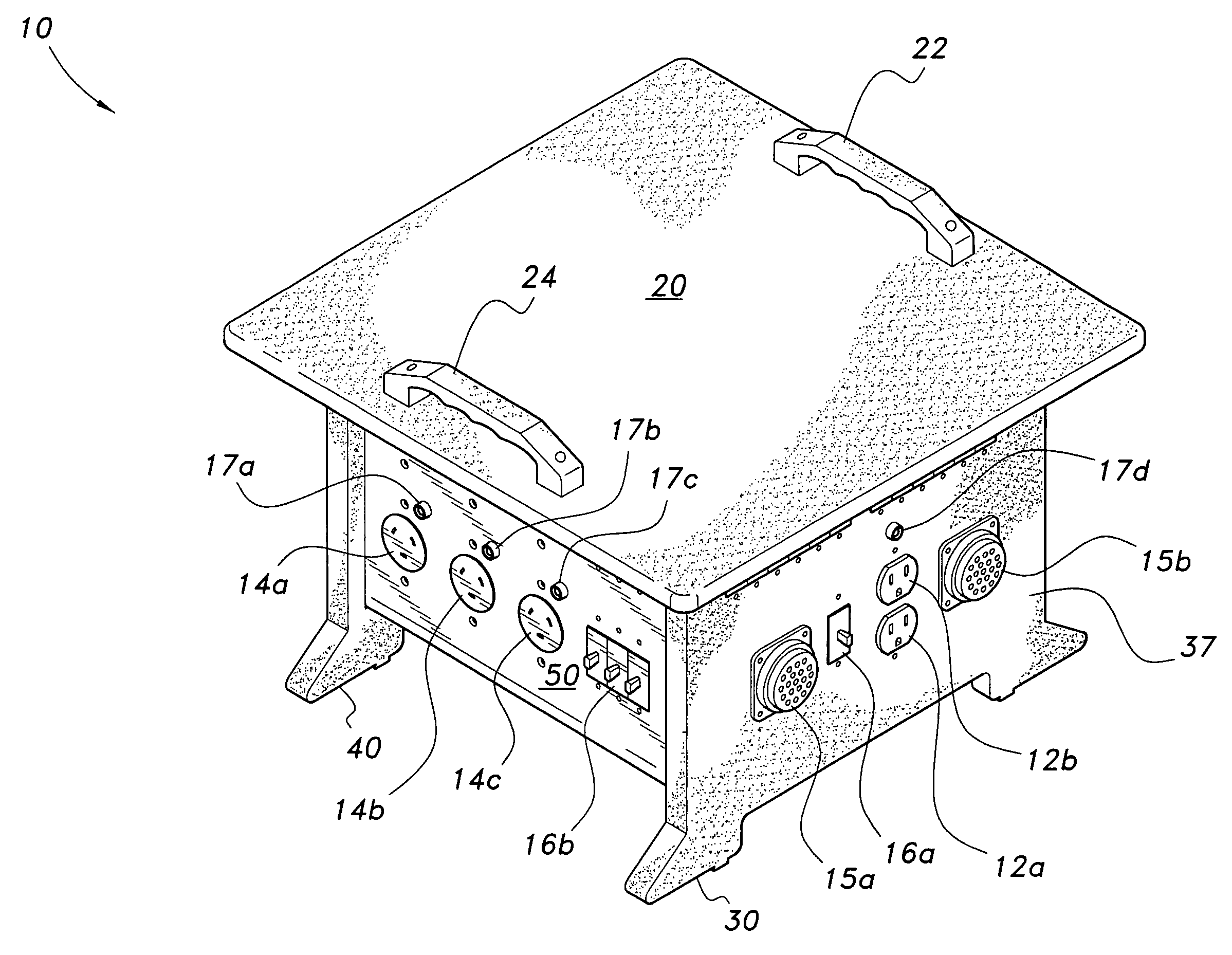
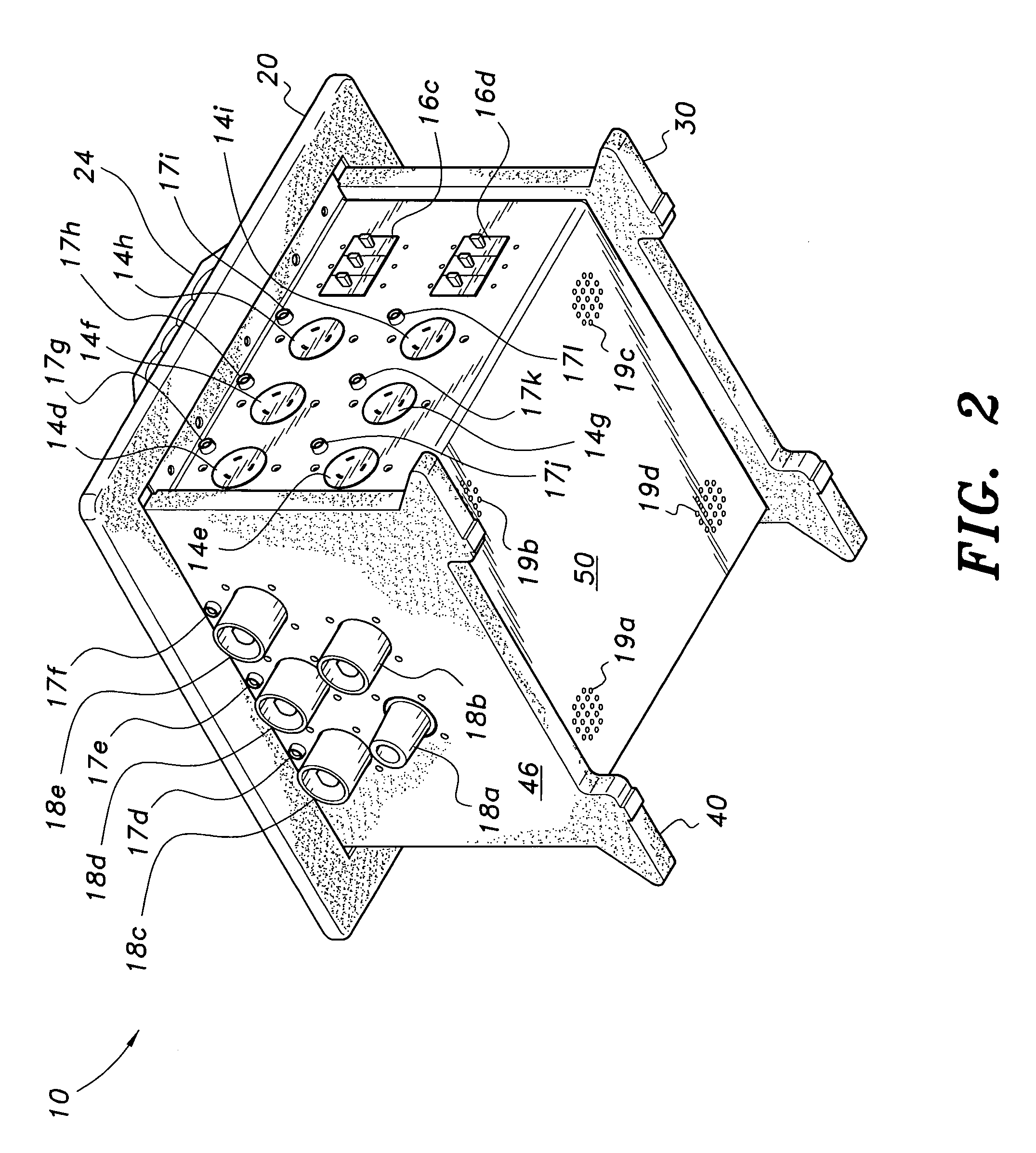
[0014]FIGS. 1 and 2 illustrate top and bottom perspective views of an embodiment of the portable electrical distribution enclosure, generally indicated with the number 10. This enclosure 10, although shown as having a box shape, can also be rectangular in shape as well. The shape of the enclosure 10 is merely dependent on use and necessities for the distribution of electrical power.

[0015]The portable power distribution enclosure 10 is for containing electrical components and associated circuitry. These components and associated circuitry provide an interface for the distribution of electrical power from a high voltage source to low voltage source or in feed through type voltage applications. UL equipment can also be used. Thus, the present invention should not be limited to one particular shape or size as long as the enclosure 10 remains portable, rugged, and useful in confined spaces such as construction sites, workplaces, aboard ships, or nearly anywhere permanent power facilities...


PUM


Abstract

The portable electrical distribution enclosure is a chassis made of anodized aluminum. The chassis has a bottom panel and two side panels. The two side panels extend parallel to each other and at right angles from the bottom panel, making the chassis rectangular. The enclosure further includes high density polyethylene front and rear panels with legs extending below the bottom panel. The front and rear legs insure that the chassis is off the ground to permit air to flow under the chassis and into vents to cool the chassis during use of the portable electrical distribution enclosure. There is also a high density polyethylene top with at least one handle. The high density polyethylene can withstand high impacts or collateral damage from surrounding environment, weather, or marine applications. Additionally, it is lightweight and nonconductive.

Description

BACKGROUND OF THE INVENTION[0001]1. Field of the Invention[0002]The present invention relates to boxes for housing electrical equipment, and particularly to a portable electrical distribution enclosure made of anodized aluminum sheet metal and molded polyethylene for providing a strong lightweight housing able to withstand collateral impacts and for protecting electrical components therein.[0003]2. Description of the Related Art[0004]It is often necessary to provide temporary electrical power for operating lights, tools, and other devices at the same time when permanent power distribution facilities have not yet been installed or are out of service due to an electrical failure. Sometimes, the temporary power distribution must be carried through or used in confined spaces that do not afford much room. This is especially true in building or repair jobs at construction sites or other workplaces such as shipyards where electrical power is needed on vessels that are being constructed or ...

Claims


Application Information

Patent Timeline
Patent Type & Authority Patents(United States)
IPC IPC(8): H02B1/26H02G3/08A47B81/00B65D88/76
CPCH02B1/52
Inventor NEUMANN, BARRYBALBI, CARMELO
Owner NEUMANN BARRY
Why Eureka
Try Eureka