
Device for diverting products sideways from a conveyor

a technology for sideways products and conveyors, which is applied in the direction of conveyors, mechanical conveyors, conveyor parts, etc., can solve the problems of construction complexity and achieve the effects of simple construction, short spacing between successive products, and high ra

Inactive Publication Date: 2010-10-26
VANDERLANDE INDURSTRIES NEDERLAND
View PDF16 Cites 16 Cited by
  • Summary
  • Abstract
  • Description
  • Claims
  • Application Information

AI Technical Summary

Benefits of technology

"The present invention provides a device for diverting products on a conveyor that can divert products quickly and with a high degree of accuracy. The device has a pivoting device that allows for smooth movement and positioning of the diverter element, even at high speeds. The device can also be positioned close to the conveyor, reducing the impact of the diverter on the product. The pivoting device includes an actuating arm and a guide device to slidably guide the diverter element. The device also has a common motor for both pivoting and driving the deflecting surface, reducing the need for a separate motor. The deflecting surface is made up of a vertically oriented diverter belt, which is passed over at least two pulleys that are rotatable about vertical axes of rotation. The device can be used in a compact manner, with a smaller conveyor length, and can operate at high speeds."

Problems solved by technology

An important drawback of such embodiments is their constructional complexity, as well as the fact that the pivot axis of one of the two sub-arms is present on the side to which the diverting of parcels takes place.

Method used


Image

  • Device for diverting products sideways from a conveyor
  • Device for diverting products sideways from a conveyor
  • Device for diverting products sideways from a conveyor

Examples


Embodiment Construction

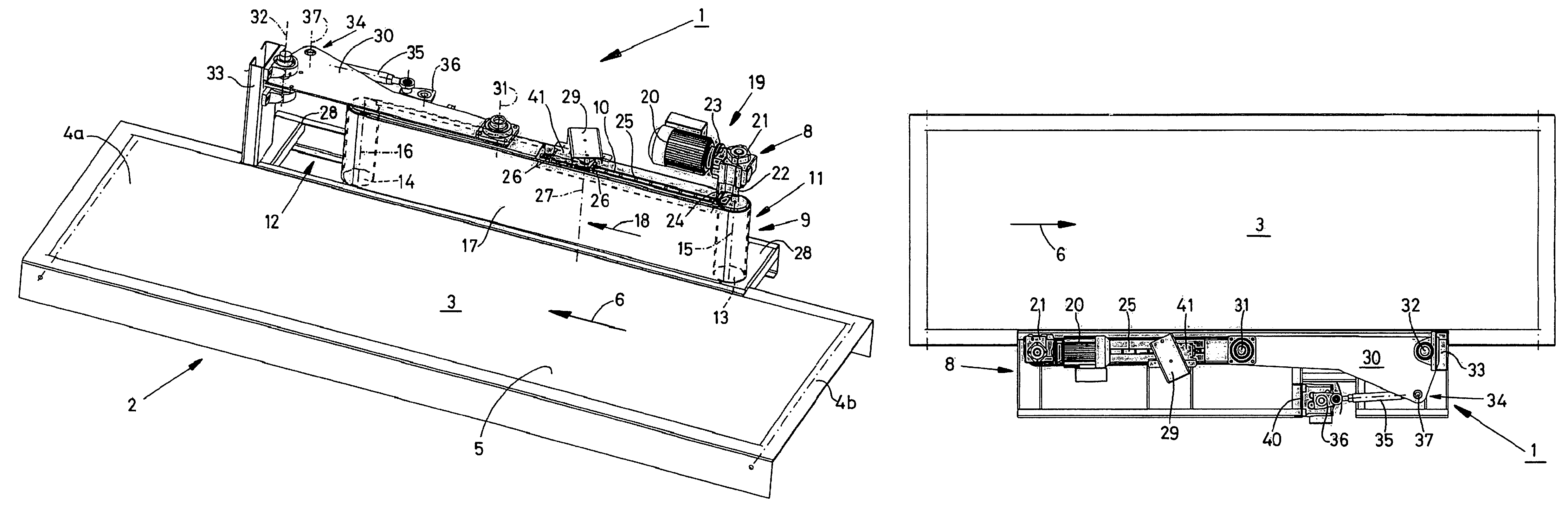
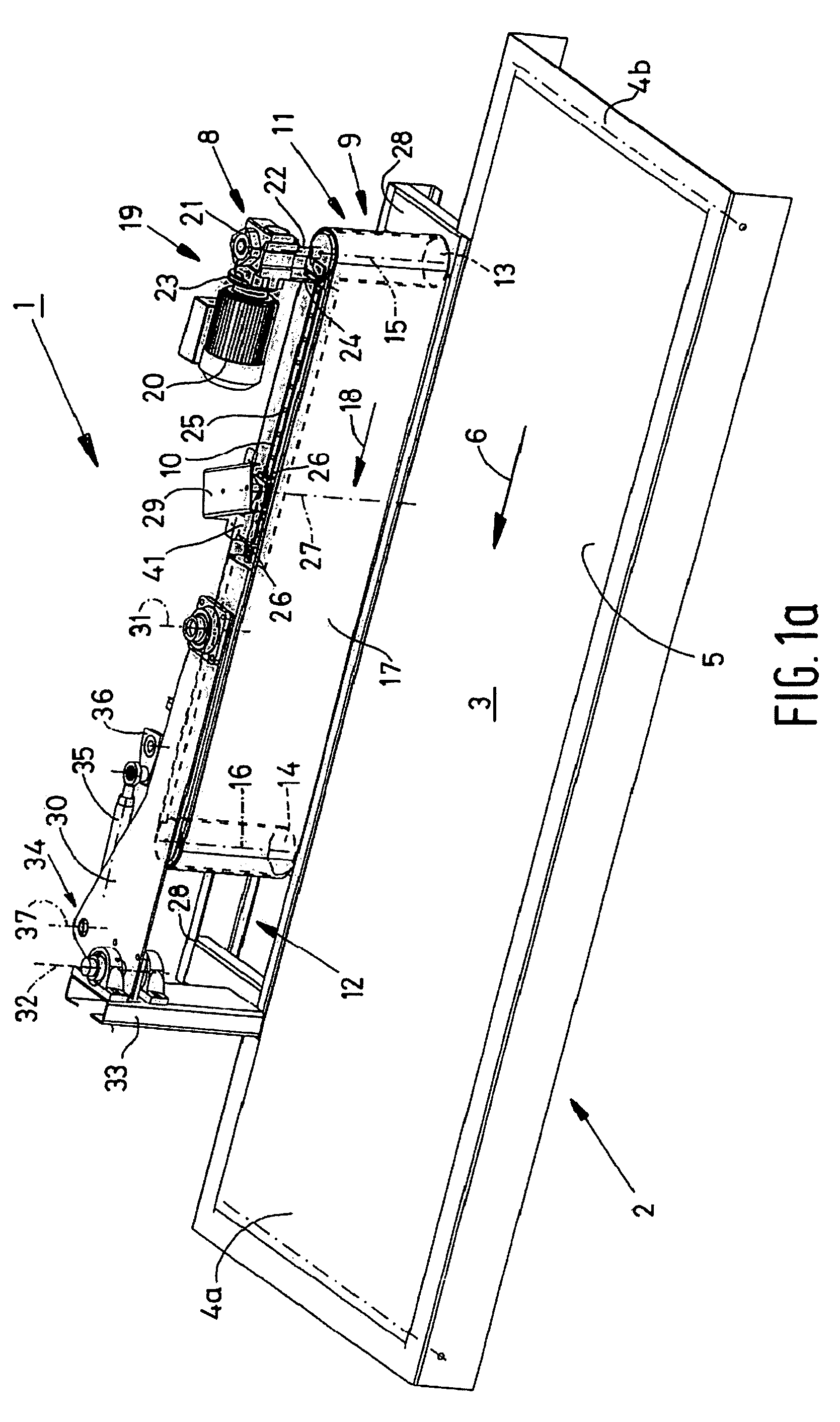
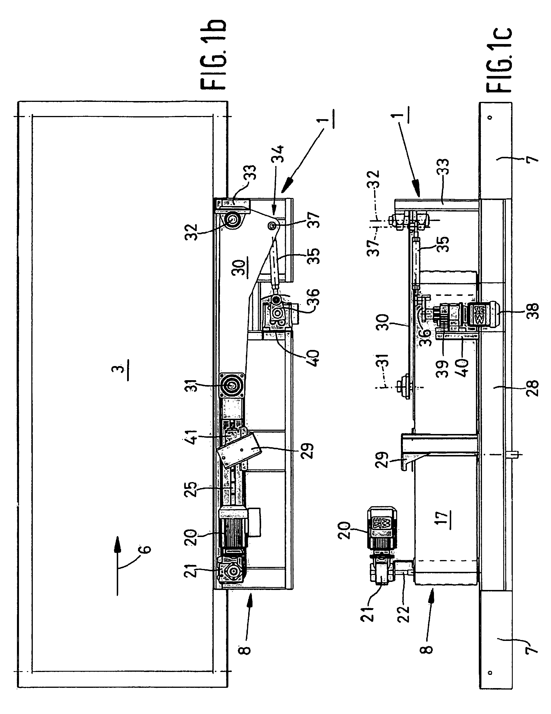
[0034]FIGS. 1a-1c and FIGS. 2a-2c are various views of a selective diverting device 1 according to a first non-limiting embodiment of the invention in, respectively, a passive position and an active position thereof. The diverting device 1 comprises a conveyor 2 (schematically shown) having a load-bearing conveying surface 3 formed by the upper side of the upper half of a conveyor belt 5 that is passed over two horizontal rotatable pulleys (not shown in FIGS. 1a and 1b), which conveyor belt is driven in the direction of transport 6 by drive means (not shown). The width of the conveyer 2 is its dimension along its axis of rotation. The pulleys are rotatably mounted (about horizontal axes of rotation 4a, 4b) in a fixed frame 7 of the conveyor 2.

[0035]A diverting unit 8 is provided on one side of the conveyor 2. The diverting unit 8 comprises a diverter arm 9, which typically includes an elongated frame 10 that defines an upstream end 11 and a downstream end 12 of the diverter arm 9. T...


PUM


Abstract

The invention provides a device for selectively diverting products sideways from a load-bearing conveying surface of a conveyor that is moving in a direction of transport, comprising a frame, an elongated diverter element having an upstream end, a downstream end and a deflecting surface there between, pivoting means for pivoting the diverter element in a reciprocal fashion about a vertical pivot axis extending on one side of the conveying surface, between a passive position, in which the diverter element extends beside the conveying surface so as to allow products to pass freely on the conveying surface, and an active position, in which the diverter element extends at least partially above the conveying surface for diverting products present on the conveying surface sideways from said conveying surface, and driving means for driving the deflecting surface with respect to a remaining part of the diverter element at least in the active position, wherein the pivoting means are arranged for translating the diverter element as well during the pivoting movement of the diverter element from the passive position to the active position and vice versa.

Description

BACKGROUND OF THE INVENTION[0001]1. Field of the Invention[0002]The present invention relates to a device for selectively diverting products sideways from a load-bearing conveying surface of a conveyor that is moving in a direction of transport.[0003]The device typically includes a frame, an elongated diverter element having an upstream end, a downstream end and a deflecting surface therebetween, pivoting means for pivoting the diverter element in a reciprocal fashion about a vertical pivot axis extending on one side of the conveying surface, between a passive position, in which the diverter element extends beside the conveying surface so as to allow products to pass freely on the conveying surface, and an active position, in which the diverter element extends at least partially above the conveying surface for diverting products present on the conveying surface sideways from said conveying surface, and drive means for driving the deflecting surface with respect to a remaining part o...

Claims


Application Information

Patent Timeline
Patent Type & Authority Patents(United States)
IPC IPC(8): B65G47/74B65G47/76
CPCB65G47/766
Inventor VAN SCHAIJK, ERWIN HENDRIKUS PETRUS MARTINUS JOHANNESVAN RIJT, BRAM ANTONIUS CAROLUS
Owner VANDERLANDE INDURSTRIES NEDERLAND
Learn More