
Grounding member for cable assembly

a technology of grounding member and cable assembly, which is applied in the direction of coupling device connection, connection contact member material, coupling device details, etc., can solve the problem of difficulty in direct soldering of conductive portions to grounding contacts

Inactive Publication Date: 2010-10-26
HON HAI PRECISION IND CO LTD
View PDF10 Cites 78 Cited by
  • Summary
  • Abstract
  • Description
  • Claims
  • Application Information

AI Technical Summary

Benefits of technology

This design facilitates reliable and efficient termination of the connector and cable by securely gripping the conductive shielding portions with the grounding member, enhancing the mechanical and electrical connection between the shielding and grounding contacts.

Problems solved by technology

However, it may be difficult to solder the conductive portions to the grounding contacts directly.

Method used


Image

  • Grounding member for cable assembly
  • Grounding member for cable assembly
  • Grounding member for cable assembly

Examples


Embodiment Construction

[0011]Reference will now be made in detail to the preferred embodiment of the present invention.

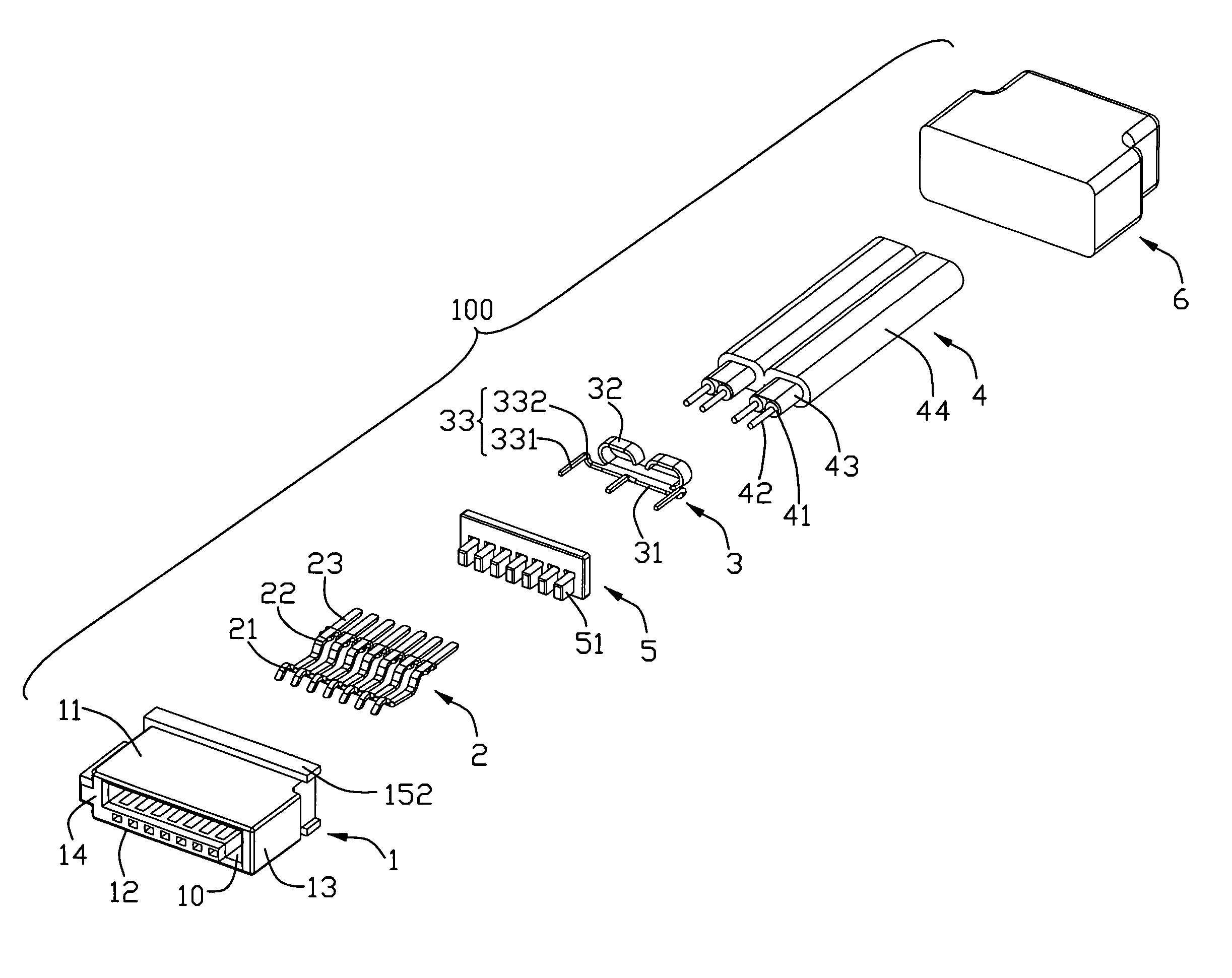
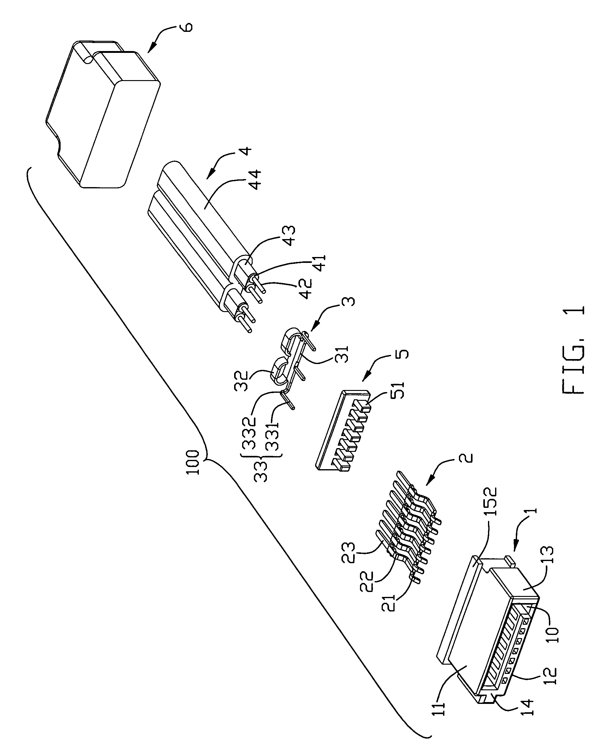
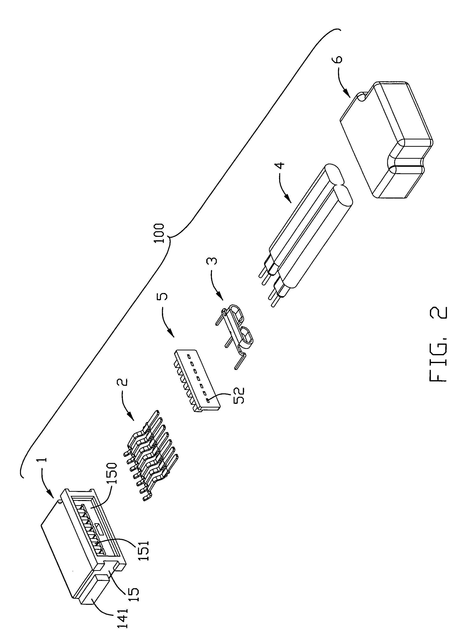
[0012]Referring to FIGS. 1-4, a cable assembly 100 in accordance to the present invention comprises an insulated housing 1, a number of contacts 2, a grounding member 3 and a cable 4.

[0013]The insulated housing 1 includes a top wall 11, a bottom wall 12, a pair of side walls 13, 14 interconnecting the top and bottom walls 11, 12 to together define an L-shaped mating port 10. A guiding member 141 is formed on an outer surface of the side wall 14. A depression portion 150 is defined in a back wall 15 of the insulated housing 1. A number of contact slots 151 are recessed forwardly from an interior side of the depression portion 150 and in communication to the mating port 10. Two flange members 152 are respectively arranged on the top and low surface of the back wall 15.

[0014]The contacts 2 has seven contact members which are arranged in a row along a transversal direction. The contact member...


PUM


Abstract

An cable assembly (100) includes an insulated housing (1) extending along a front-to-back direction; a plurality of contacts (2) arranged in a row and supported by the insulated housing, said contacts including three grounding contact members spaced by two pair of signal contact members; a cable (4) including two juxtaposed differential wire pairs (41) respectively enclosed by conductive shielding portions (43); a grounding member (3) including a main portion (31), three finger portions (33) extending forwardly from a front side of the main portion and two arm portions (32) formed at lateral sides of a rear segment of the main portion, said grounding member (3) securely engaged with the cable via the two arm portions thereof griping the conductive shielding portions; and the finger portions soldered to the grounding contact members, and inner conductors of the differential pairs soldered to the signal contact members, respectively.

Description

FIELD OF THE INVENTION[0001]The present invention generally relates to a cable assembly, and more particularly to a grounding member used for connecting a shielding member of a cable and grounding contacts of an electrical connector.DESCRIPTION OF PRIOR ART[0002]Serial Advanced Technology Attachment (SATA) is an art that is different from Advanced Technology Attachment (PATA). At present, transmitting rate of a device utilizing SATA has already up to 150 MB / s or more, which is much higher than an equipment adopting PATA.[0003]A SATA cable assembly is used for connecting a Hard Disk (HD) and a main board (MB) of a computer. The SATA cable assembly used for transmitting signals includes a connector and a cable connected thereto. The connector has two pair of signal contacts spaced apart by three grounding contacts. The cable also has two pair of wires coupled to the corresponding signal contacts. Each of the pair of wires is further shielded by conductive portions for coupled to the g...

Claims


Application Information

Patent Timeline
Patent Type & Authority Patents(United States)
IPC IPC(8): H01R4/66
CPCH01R9/034H01R13/6585H01R13/6592H01R12/592H01R13/65914
Inventor KO, DAVID TSO-CHINTSAI, YEN-CHAOWANG, TAO
Owner HON HAI PRECISION IND CO LTD
Learn More