
Phantom powered pedals

a pedal and phantom technology, applied in the field of phantom powered pedals, can solve the problems of cumbersome power adapters, messy, and inconvenient use, and achieve the effects of convenient use, convenient use, and convenient us

Active Publication Date: 2010-10-26
ROBLING JASON O +1
View PDF24 Cites 24 Cited by
  • Summary
  • Abstract
  • Description
  • Claims
  • Application Information

AI Technical Summary

Benefits of technology

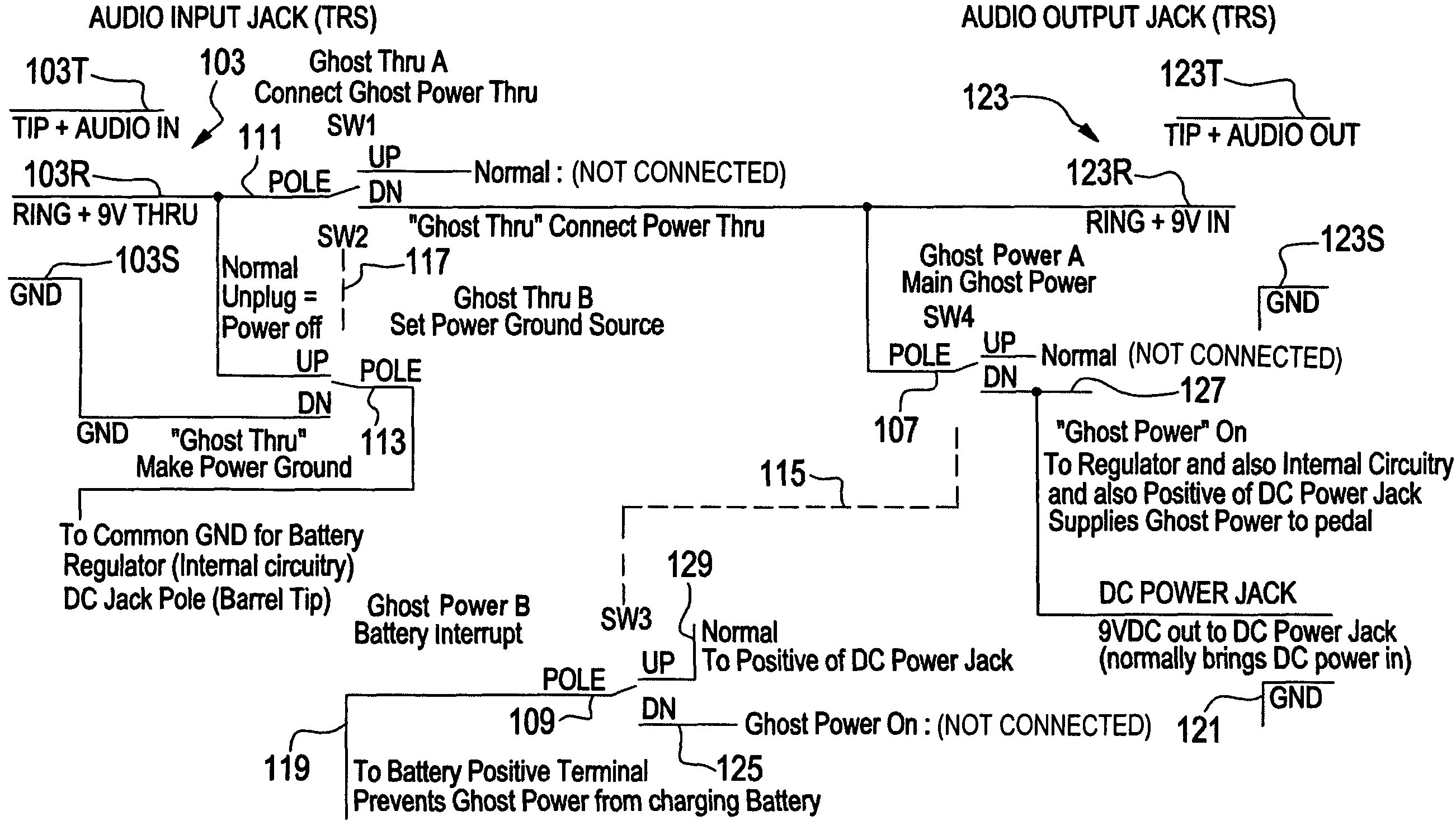
[0004]Microphones are currently phantom powered but use a different type of cable and different impedance than guitarists / instrument cables. Multiple microphones are not linked together. Effects pedals can be and frequently are linked together in-line. Each pedal provides a different effect on the audio signals.
[0013]Switching in the phantom powered pedals could be accomplished by any electromechanical means, be it ganged or independent switches, and be of any variety; including toggle, DIP, rotary, push-button, slide, CMOS or similar, or relay or other electromechanical contact, directly or indirectly actuated mechanically or electrically or via software and / or remote control. Whether using separate jacks or switches—the same changes of DC power function are performed. One feature of the phantom powered effect pedal is the ability to send the DC power out through the existing DC-in jack, with the potential of placing additional DC in / out jacks so that a switch would not be needed.

Problems solved by technology

Both of these methods (batteries and adapters) are frustrating to the musician.
Batteries can die during a performance and are expensive.
Power adapters are cumbersome, messy, and pose a hazard on stages where performers or other people can trip over the extraneous wires.

Method used


Image

  • Phantom powered pedals
  • Phantom powered pedals
  • Phantom powered pedals

Examples


Embodiment Construction

[0026]The drawings are for the purpose of illustrating the invention's preferred embodiments and not for the purpose of limiting the invention.

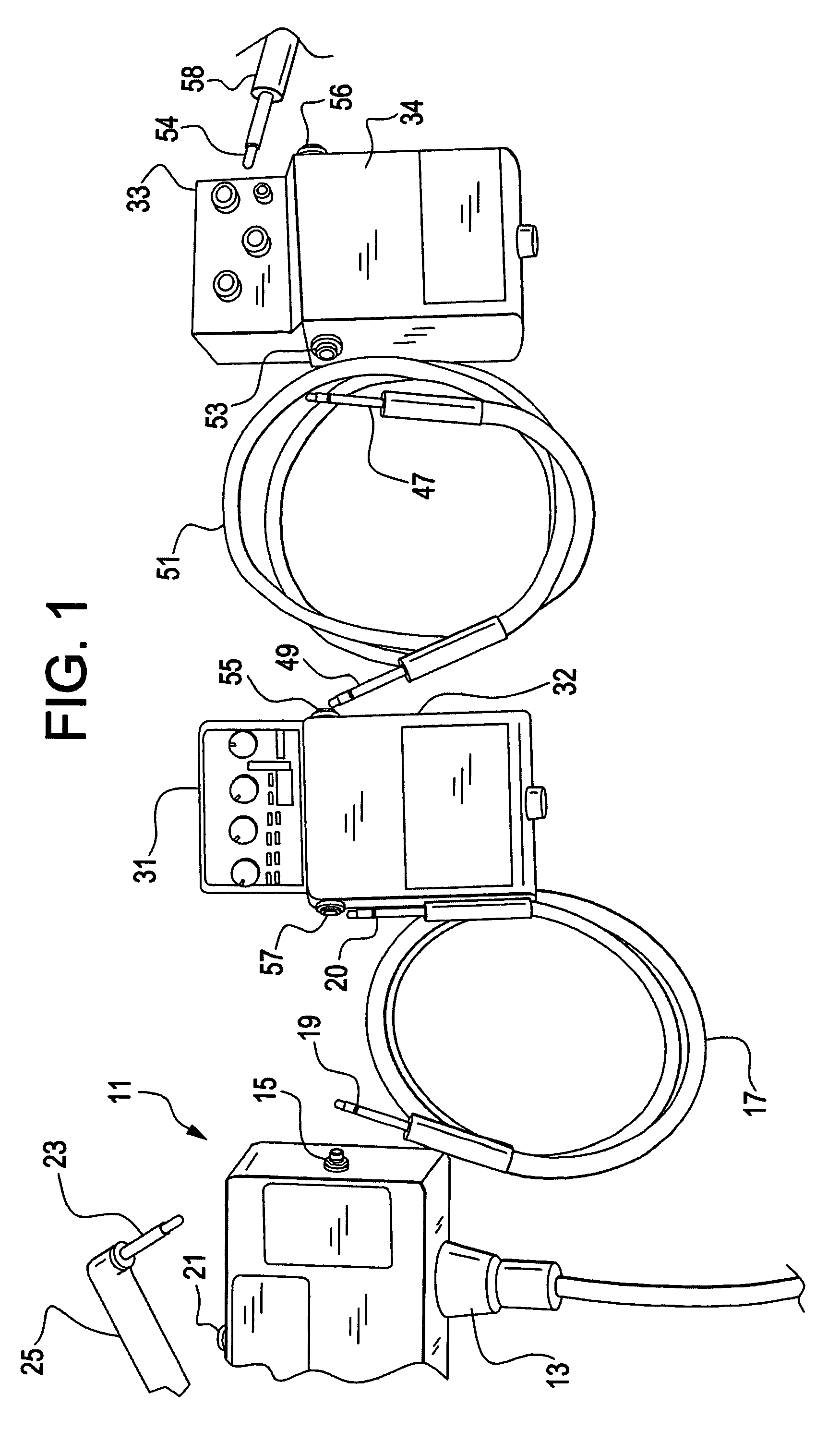
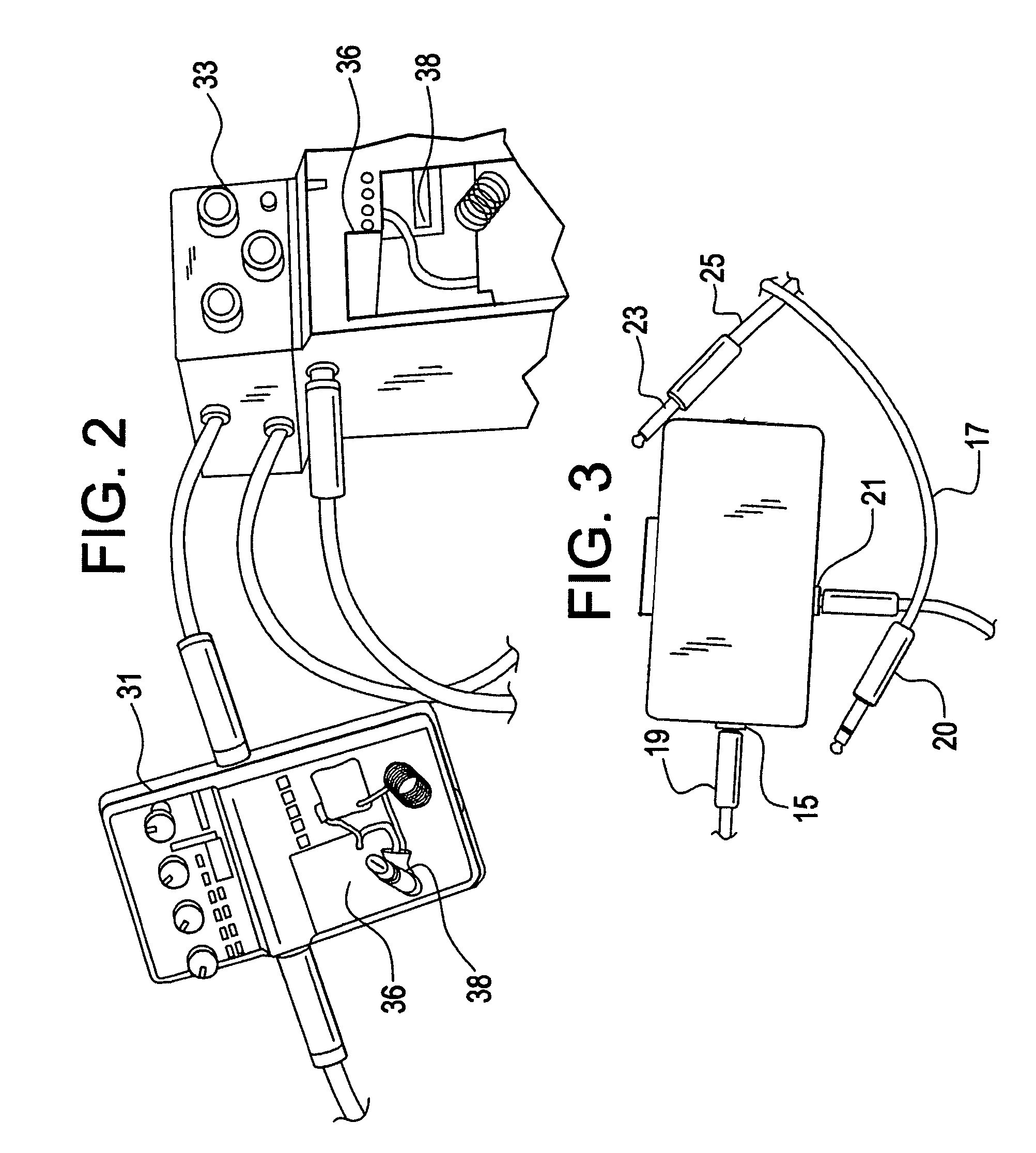
[0027]FIG. 1 shows the DC power supply box 11, which includes an AC power input connector 13, a step-down transformer and an AC-DC converter within the box 11, a three-wire cable jack 15 for connecting a three-wire cable 17 for audio signal input to the box 11 and phantom power output from the box 11 and a two-wire audio signal output cable jack 21 for receiving a connector 23 on a two-wire audio signal output cable 25 to an amplifier. The three-wire cable 17 has a first end tip-ring-sleeve (TRS) connector 19 for connection to the three wire jack 15 and a second end tip-ring-sleeve connector 20 for connecting to effects pedal 31, to provide phantom power from box 11 to the effects pedal and to transfer audio signals from the effects pedal through the box 11 to the amplifier.

[0028]Effects pedal 33 is connected to the effects pedal 31 with tip-...


PUM


Abstract

Musical instrument effects pedals are powered from adjacent pedals by providing electrical connectors between adjacent pedals and by providing tip-ring-sleeve jacks in the pedals and three wire connectors with tip-ring-sleeve connectors, which carry sound signals from an instrument through sequential pedals and electrical power in an opposite direction to the pedals.

Description

[0001]This application claims the benefit of U.S. Provisional Application No. 60 / 963,530, filed Aug. 6, 2007, which is hereby incorporated by reference in its entirety.SUMMARY OF THE INVENTION[0002]The invention provides and controls phantom power to a chain of pedals from a power supply and audio signal connecting box.[0003]A tip-ring-sleeve connector cable provides power from the power supply box to a first pedal. Additional pedals may be connected by tip-ring-sleeve connector cables. A tip-sleeve connector cable connects the last distal pedal to a guitar. Audio signals from the guitar are carried to the last pedal by the tip-sleeve cable. Pedal-modified signals are carried to the power supply and audio signal connecting box through the tip-ring-sleeve cables. The box is connected to an amplifier by a tip-sleeve connector cable.[0004]Microphones are currently phantom powered but use a different type of cable and different impedance than guitarists / instrument cables. Multiple micro...

Claims


Application Information

Patent Timeline
Patent Type & Authority Patents(United States)
IPC IPC(8): G10H3/00
CPCG10H1/348G10H3/186
Inventor ROBLING, JASON O.MILBERT, MICHAEL B.
Owner ROBLING JASON O
Learn More