Method for adjusting trip sensitivity of thermal overload protection apparatus

a technology for thermal overload protection and trip sensitivity, which is applied in the direction of circuit-breaking switches, relays, and protective devices, etc., can solve the problems of inability to ensure the reliability of trip operation, and the user manually rotating the knob cannot accurately adjust the sensitivity of the devi

Active Publication Date: 2010-10-26
LG IND SYST CO LTD
View PDF49 Cites 9 Cited by
  • Summary
  • Abstract
  • Description
  • Claims
  • Application Information

AI Technical Summary

Benefits of technology

[0016]Therefore, a non-limiting feature of the present invention is directed to providing a method for adjusting a trip sensitivity of a thermal overload protection apparatus which is capable of precisely and effectively adjusting a trip operation sensitivity at a time of an overload (overcurrent) occurrence.

Problems solved by technology

And even though the trip operation is implemented by the cooperation between the trip load upon the trip apparatus and the elastic stress of the bimetal, an adjusting that reduces the remaining distance, which is the trip operation allowance Δy only to 0 (zero), has a drawback in that it is not capable of ensuring the reliability of a trip operation.
However, the stop in the manual rotating manipulation has actually a very small velocity (not zero), so there is a drawback that a user manually rotating the knob cannot accurately adjust the sensitivity of the device.

Method used


Image

  • Method for adjusting trip sensitivity of thermal overload protection apparatus
  • Method for adjusting trip sensitivity of thermal overload protection apparatus
  • Method for adjusting trip sensitivity of thermal overload protection apparatus

Examples


Embodiment Construction

[0032]A description will now be given in detail of the preferred embodiments of the present invention, examples of which are illustrated in the accompanying drawings.

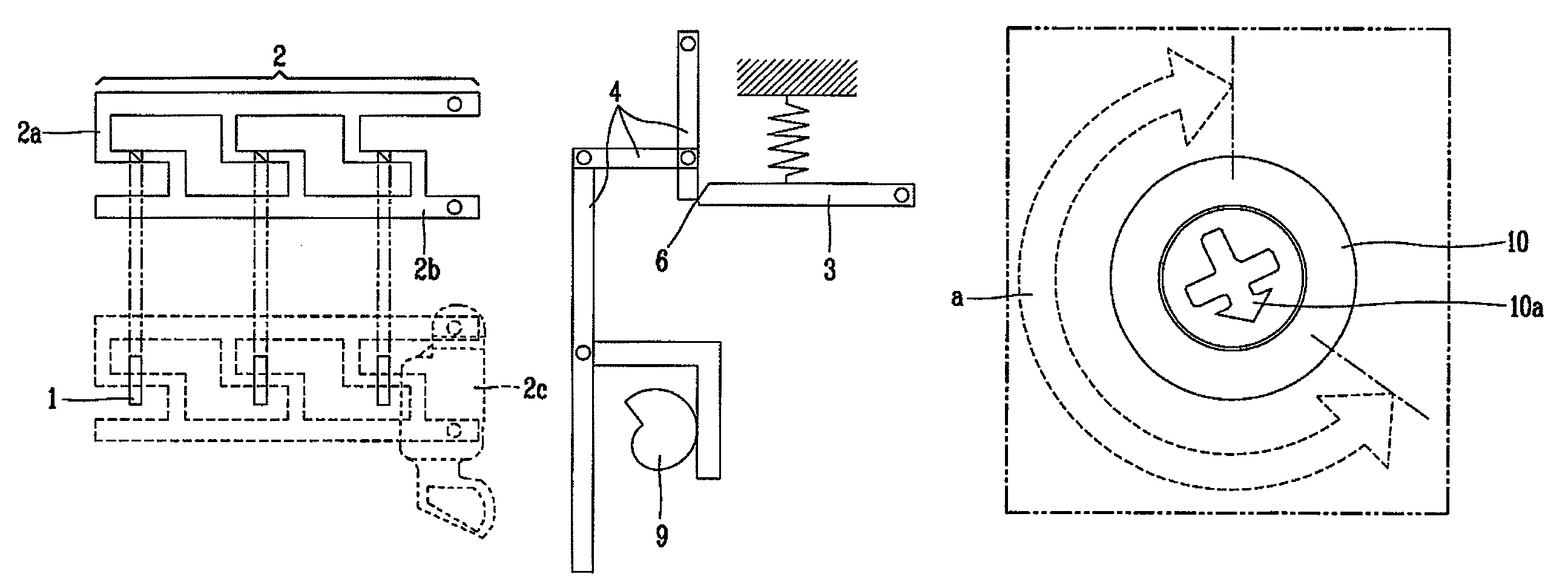
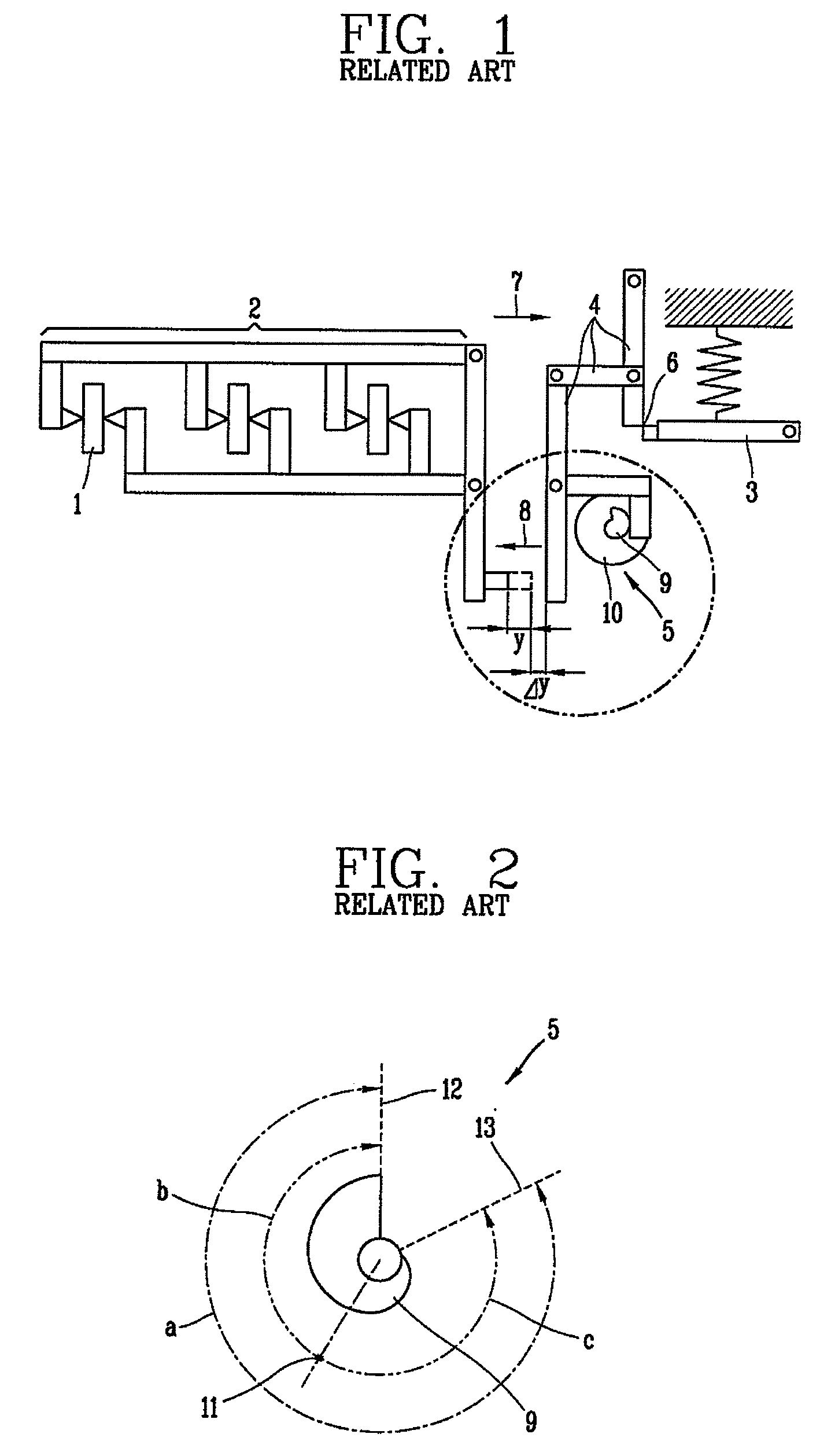
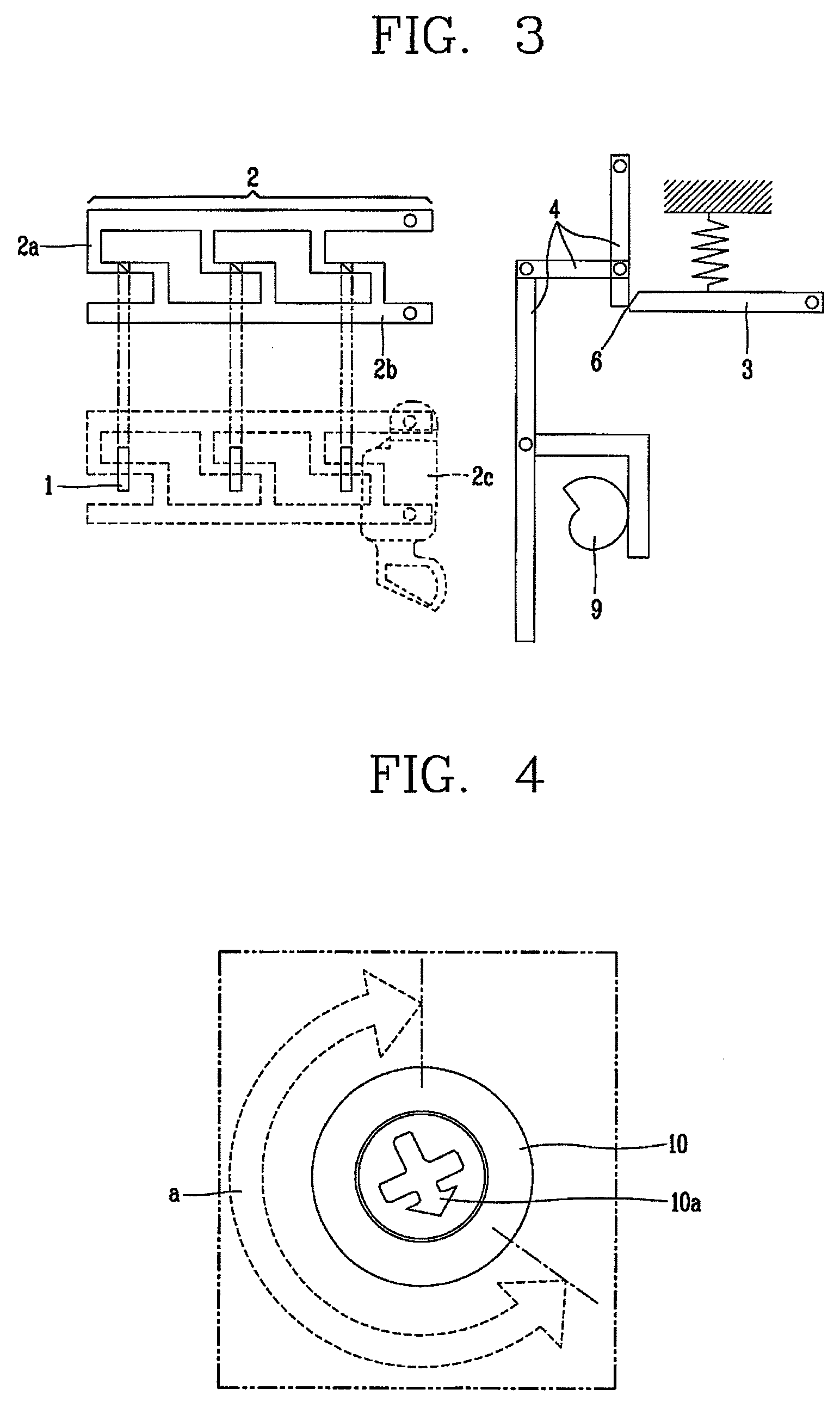
[0033]FIG. 3 is a diagram schematically showing a configuration of a thermal overload protection apparatus in accordance with the present invention, and FIG. 4 is a diagram showing a relation between an adjusting knob and an adjusting area in the thermal overload protection apparatus in accordance with the present invention, and FIG. 5 is a view showing a moment that the thermal overload protection apparatus in accordance with the present invention performs a trip operation.

[0034]Referring to FIGS. 3 to 5, a configuration of the thermal overload protection apparatus in accordance with the present invention and operation thereof will be described.

[0035]The thermal overload protection apparatus in accordance with the present invention includes bimetals 1 for providing a driving force for a trip operation by bending when a...


PUM


Abstract

A method for adjusting a trip sensitivity in a thermal overload protection apparatus, including setting an adjusting reference point; measuring a normal position of bimetals; measuring a moving distance at a time of trip operation of a trip latch mechanism; deciding an assembling position of a shifter mechanism based on the measured moving distance at the time of trip operation of the trip latch mechanism, information on a trip distance between a pre-determined shifter mechanism and the trip latch mechanism and information on a size of the shifter mechanism; conducting a predetermined overcurrent to the thermal overload protection apparatus; measuring a conducting time of the overcurrent until a trip event; calculating a difference between the conducting time measured in the measuring step and a predetermined trip time by converting a rotation angle; and marking a graduation of a set trip operation current by the rotation angle calculated in the calculating step.

Description

BACKGROUND OF THE INVENTION[0001]1. Field of the Invention[0002]The present invention relates to an apparatus for protecting a motor from an overload (overcurrent), more particularly, to a method for setting and adjusting a trip sensitivity in a thermal overload protection apparatus.[0003]2. Description of the Related Art[0004]An overload protecting function, a basic function of a thermal overload trip apparatus, is implemented by performing a trip operation when an overload or overcurrent within a current range satisfying a pre-set condition for the trip operation is generated in an electric circuit. The current range may refer to a current range for the trip operation according to an IEC (International Electrotechnical Commission) standard specified as an international electrical standard. For example, a condition for the trip operation is that the trip operation should be performed within two hours when a current corresponding to 1.2 times a rated current is conducted in a circui...

Claims


Application Information

Patent Timeline
Patent Type & Authority Patents(United States)
IPC IPC(8): H01H71/74H02H5/04H01H71/16
CPCH01H69/01H01H71/7445H01H71/162H01H2071/167H01H71/16
Inventor SONG, KI-BONG
Owner LG IND SYST CO LTD
Why Eureka
Try Eureka