
Digital iterative gain control

a gain control and digital technology, applied in the field of optical communication, can solve the problems of invading the reception of ir signals by close-by fluorescent lamps, limited power that can be applied to ir transmitters, and dominating noise,

Active Publication Date: 2010-10-26
INNCOM INT INC
View PDF29 Cites 14 Cited by
  • Summary
  • Abstract
  • Description
  • Claims
  • Application Information

AI Technical Summary

Problems solved by technology

The power that can be applied to the IR transmitter is limited by the rating of commercially affordable IR LEDs and safety considerations that preclude the use of lasers.
In IR systems, the dominant noise is caused by ambient light sources such as the sun and incandescent and fluorescent lamps.
Noise generated by close-by fluorescent lamps is intrusive for IR signal reception, as it presents high levels of energy in the optical wavelength of the IR signal.
Fluorescent lamps that use electronic high-frequency ballasts are particularly troublesome, as they generate IR noise with modulation characteristics that are similar to the modulation schemes found to be most effective for IR communication networks.
However, in IR communication systems used in the vicinity of man-made light sources, the dominant noise source is shot noise.
The limitation of the Teich system is that it encumbers the decoding function of the receiver.

Method used


Image

  • Digital iterative gain control
  • Digital iterative gain control
  • Digital iterative gain control

Examples


Embodiment Construction

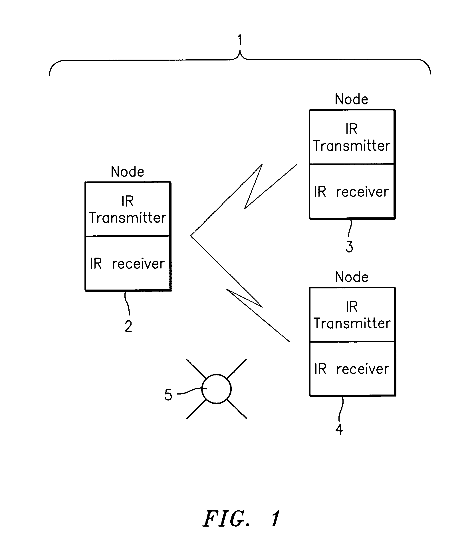
[0024]With reference to FIG. 1, an IR network 1 comprises at least two nodes identified as 2 and 3. Additional nodes such as 4 can be included. Each node 2, 3, and 4 includes an IR transmitter 6 and an IR receiver 7. The network 1 may be required to operate in the presence of IR interference sources such as a fluorescent and / or incandescent lamp 5. The IR signal that is transmitted, for example, from node 2 arrives at node 4 mixed with noise generated by lamp 5.

[0025]The IR receiver 7 is useable, for example, in an IR communication network used for the exchange of data and the control of apparatus in a space defined by the wails of a room. Each node 2, 3, or 4 can initiate a communication session, where it sends information or commands to another node 2, 3, or 4. The addressed node 2, 3, or 4 may respond in half-duplex protocol, after the completion of the transmission of the packet from the initiating node. Before initiating a new session, a node verifies that there are no sessions...


PUM


Abstract

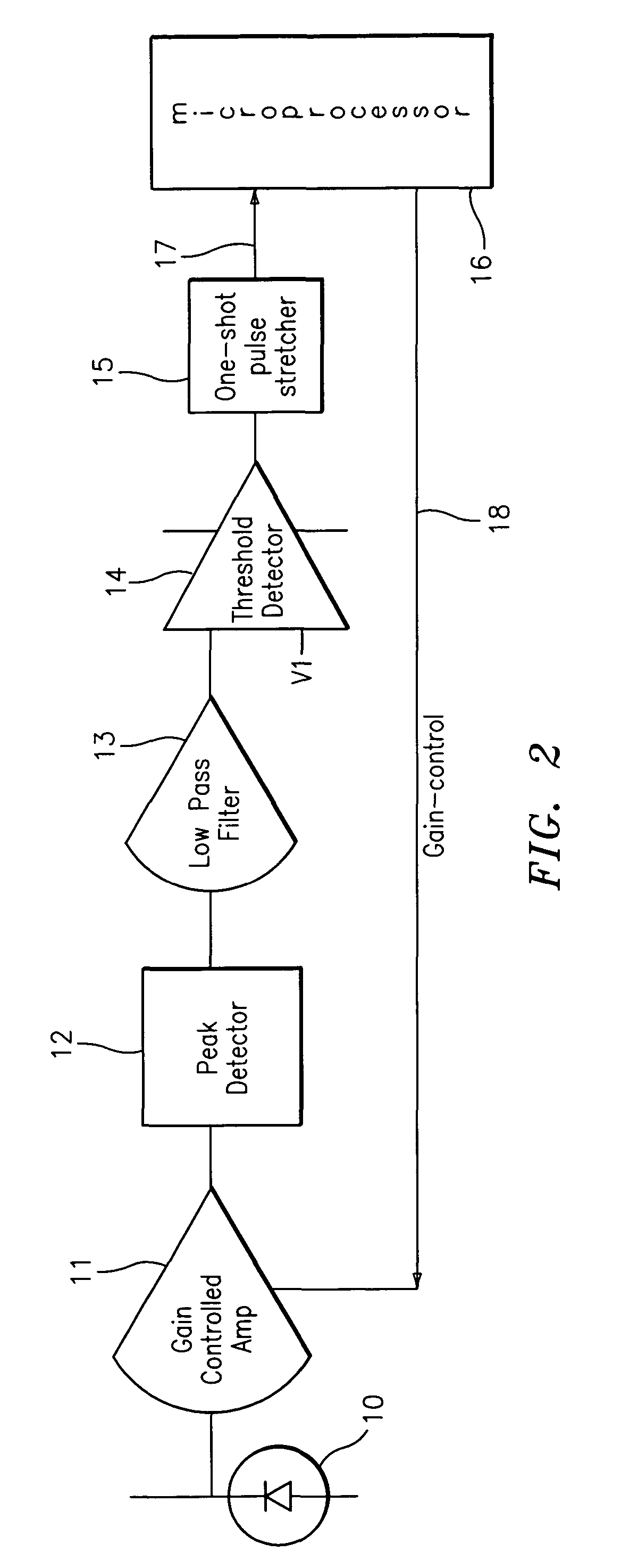
In an IR communication network, a method is described to optimize channel performance in the presence of strong and varying IR interference. The method controls of the channel gain based on quantitative measurement of the channel noise.

Description

CROSS-REFERENCE TO RELATED APPLICATIONS[0001]This application claims the benefit of U.S. provisional application No. 60 / 400,480, filed Aug. 1, 2002 the contents of which are incorporated by reference herein in their entirety.BACKGROUND OF THE INVENTION[0002]The present invention is related to optical communication, and more particularly to wireless communications using infrared (IR) wavelength transmitters and receivers.[0003]IR communication is often favored over radio frequency (RF) wireless communication for relatively short distances because of its immunity to most sources of noise. The IR signals are also easily contained within a room, as they do not penetrate walls. This limitation is actually a significant advantage in multi-dwelling buildings such as hotels and apartment buildings, as the signal from one room will not interfere with the signals in another room[0004]One popular application for IR communication within rooms is for the control of appliances, such as TV and lig...

Claims


Application Information

Patent Timeline
Patent Type & Authority Patents(United States)
IPC IPC(8): H04B10/06H03G3/30H04B10/10
CPCH03G3/3084H04B10/114
Inventor ROOSLI, PHILIPPGIFFONE, RALPHSHAH, HAZRAT
Owner INNCOM INT INC
Learn More