Liquid ejection head
a liquid ejection and head technology, applied in the field of liquid ejection head, can solve the problems of increasing seriousness of the effect of droplet printing, reducing the image quality caused by satellite droplets, and not being able to control the landing location of satellite droplets, etc., and achieve the effect of satisfying printing
- Summary
- Abstract
- Description
- Claims
- Application Information
AI Technical Summary
Benefits of technology
Problems solved by technology
Method used
Image
Examples
first embodiment
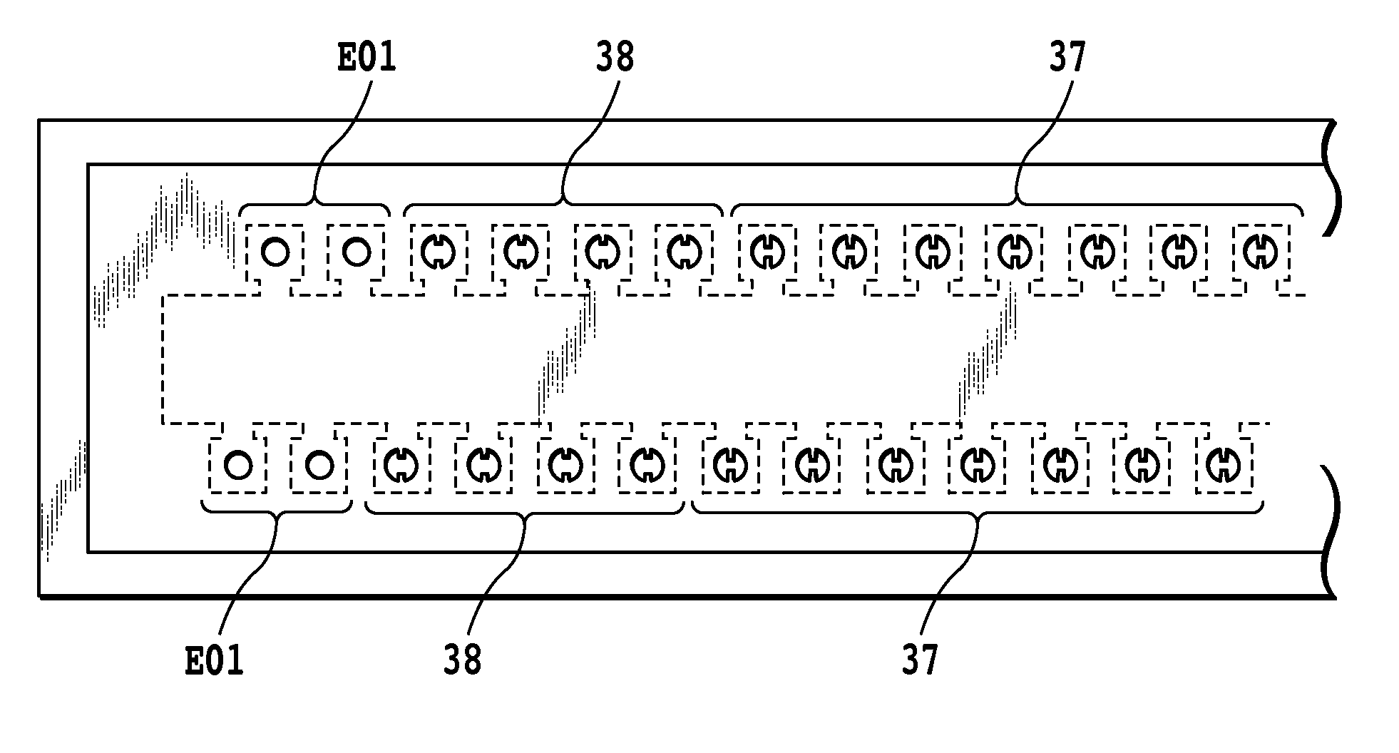
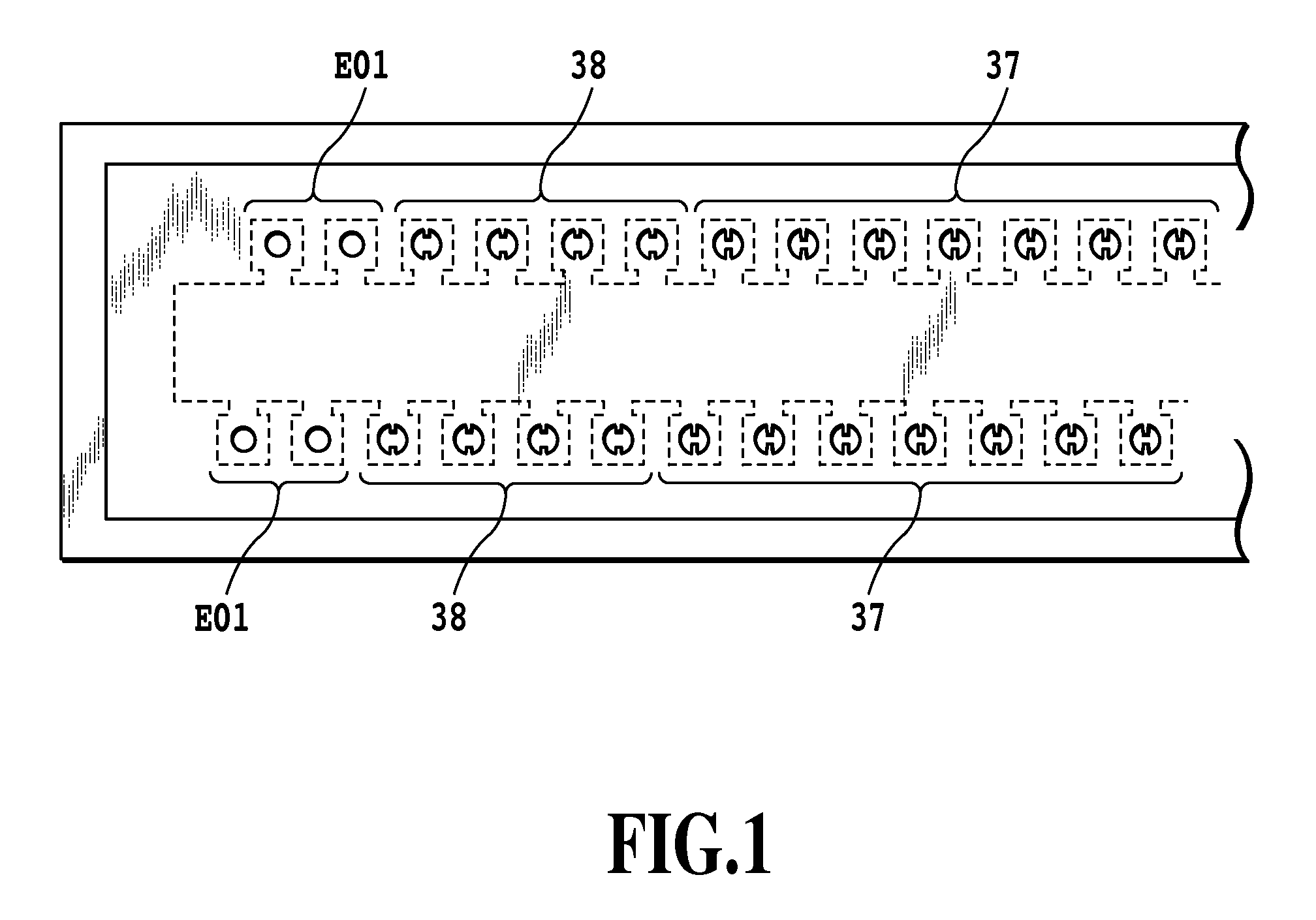
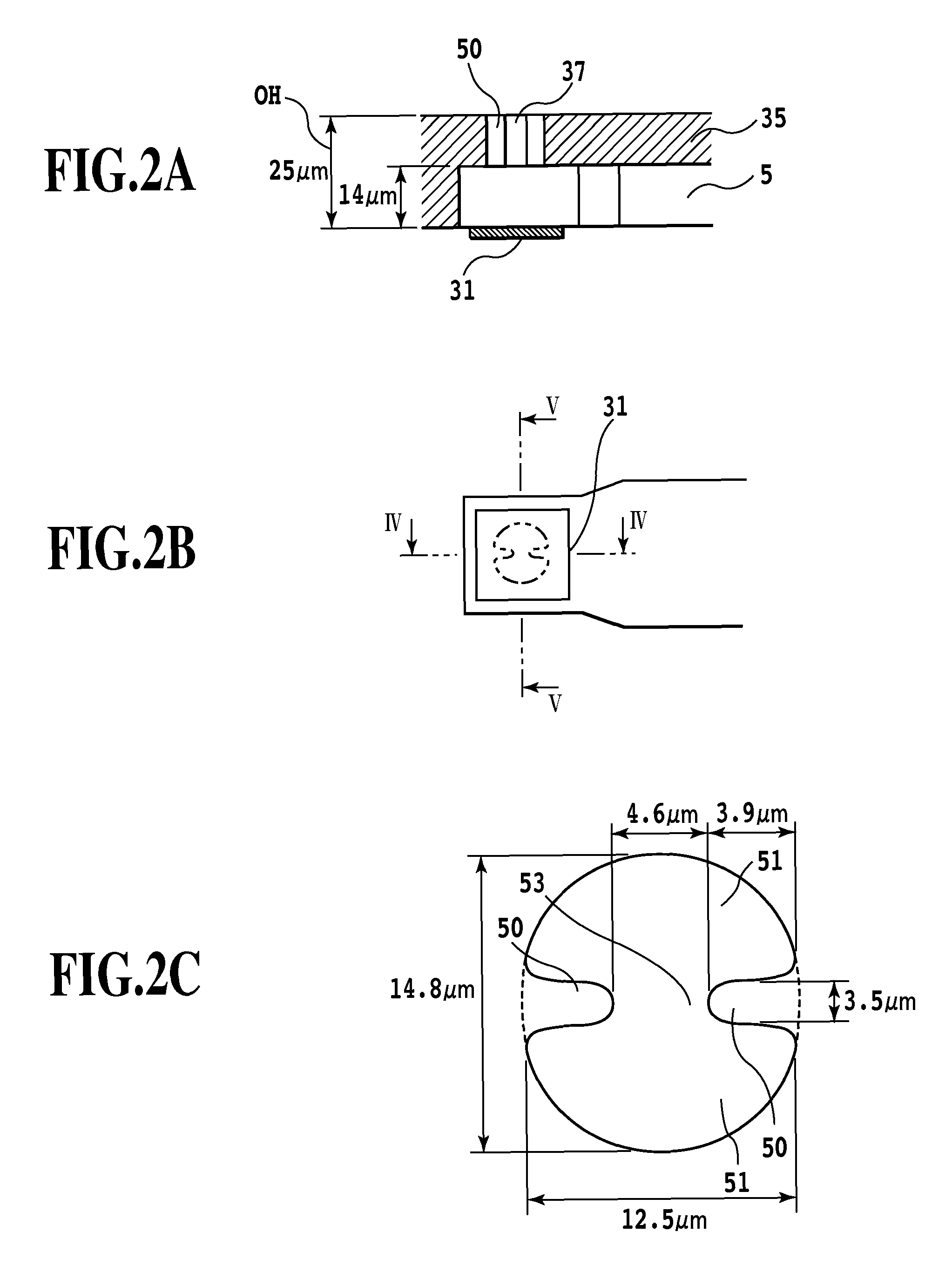
[0048]A first embodiment of the present invention will be described below with reference to the drawings. FIG. 20 is a schematically perspective view illustrating a major portion of an ink-jet printing apparatus to which the liquid ejection head of the present invention is applicable. The ink-jet printing apparatus includes a casing 1008 and a transport unit 1030 provided inside the casing 1008 in the longitudinal direction for feeding a paper sheet 1028, which is a recoding medium, in a direction indicated by the arrow P (hereinafter referred to as “direction P”). The ink-jet printing apparatus further includes a printing unit 1010 and a moving drive unit 1006. The printing unit 1010 is movable in a direction indicated by the arrow S (hereinafter referred to as “direction S”) at approximately right angles to the direction P, which is the direction of carrying the paper sheet 1028. The moving drive unit 1006 is capable of shuttling the printing unit 1010.
[0049]The transport unit 103...
second embodiment
[0089]A liquid ejection head in a second embodiment differs in the shape of each of the end-located ejection orifices from the shape of the ejection orifice described in the first embodiment. The structure of other components is similar to that in the liquid ejection head in the first embodiment, and details are omitted.
[0090]As in the case of the first embodiment, the liquid ejection head in the second embodiment comprises the end-located ejection orifices and the ejection orifices located in the central portion which are provided with the protrusions. One of the two protrusions provided in each of the end-located ejection orifices is shorter than the other protrusion.
[0091]FIG. 12 is a diagram illustrating a part of the liquid ejection head of the second embodiment. Each of the end-located ejection orifices 40 are provided with a longer protrusion and a shorter protrusion. In this manner, only in the end-located ejection orifices, one of the protrusions in each ejection orifice is...
third embodiment
[0095]A liquid ejection head in a third embodiment differs in the shape of each of the end-located ejection orifices from the shape of the ejection orifice described in the first embodiment. The structure of other components is similar to that in the first and second embodiments.
[0096]FIG. 16A is a diagram illustrating an end-located ejection orifice in a third embodiment. FIG. 16B is a diagram illustrating an end-located ejection orifice in a modified example of the third embodiment.
[0097]In the end-located ejection orifices of the liquid ejection head of the third embodiment, the closer to the end of the ejection orifice row, the shorter the length of the protrusions provided in the end-located ejection orifices as illustrated in FIG. 16A. The closer to the endmost-located ejection orifice, the more easily the defective conditions deteriorating smooth ink-ejection after the lapse of a predetermined time period occur. To avoid this, the ejection orifices provided with the protrusio...
PUM
 Abstract
Description
Claims
Application Information
 - R&D
- Intellectual Property
- Life Sciences
- Materials
- Tech Scout
- Unparalleled Data Quality
- Higher Quality Content
- 60% Fewer Hallucinations
Browse by: Latest US Patents, China's latest patents, Technical Efficacy Thesaurus, Application Domain, Technology Topic, Popular Technical Reports.
© 2025 PatSnap. All rights reserved.Legal|Privacy policy|Modern Slavery Act Transparency Statement|Sitemap|About US| Contact US: help@patsnap.com


