Control device for vehicle power transmission device

a technology of power transmission device and control device, which is applied in the direction of electric propulsion mounting, vehicle sub-unit features, etc., can solve the problems of shift shock, change in input torque, and inability to smoothly carry out the transition to the driving state. to achieve the effect of reducing the shift shock

Inactive Publication Date: 2010-11-02
TOYOTA JIDOSHA KK +1
View PDF13 Cites 20 Cited by
  • Summary
  • Abstract
  • Description
  • Claims
  • Application Information

AI Technical Summary

Benefits of technology

[0011]The invention has been accomplished against the background of the aforementioned circumstances, and provides a control device in a vehicle power transmission device that includes an electrical differential motion portion and a power connection-disconnection device, the control device being capable of reducing the shift shock when the vehicle power transmission device is switched from the non-driving state to the driving state.
[0013]According to the control device for the vehicle power transmission device, in the case where a change in the input torque to the vehicle power transmission device occurs during a switch of the state of the vehicle power transmission device from the non-driving state to the driving state, the transmission capacity of the power connection-disconnection device is lessened in comparison with when the change in the input torque does not occur. Therefore, the transmission capacity of the power connection-disconnection device during a transitional state occurring at the start of connection of the power is changed according to changes in the input torque. Hence, the shift shock can be reduced even in the case where the input torque to the vehicle power transmission device changes during the switch of the state of the vehicle power transmission device from the non-driving state to the driving state.
[0015]According to the control device for the vehicle power transmission device, in the case where a change in the input torque to the vehicle power transmission device occurs during a switch of the state of the vehicle power transmission device from the non-driving state to the driving state, the start of the connection of power by the power connection-disconnection device is delayed in comparison with the case where the change in the input torque does not occur. Therefore, the engagement elements are engaged after the change in the input torque has converged or has become diminished. Hence, the shift shock can be reduced even in the case where the input torque to the vehicle power transmission device changes during the switch of the state of the vehicle power transmission device from the non-driving state to the driving state.

Problems solved by technology

If the state of a motive power source changes when the vehicle power transmission device is switched from the non-driving state to the driving state, there is possibility that the switching to the driving state may not be smoothly carried out or a shift shock may occur.
However, during a low engine efficiency state, for example, when the vehicle is started from a halt state, or the like, the vehicle is run only by the electric motor.
However, if the state of charge (SOC) of the electricity storage device provided in the vehicle is low, the engine needs to be driven in order to generate electric power for charging the electricity storage device.
In the case where the foregoing driving of the engine is performed when the ratio shift portion is switched from the non-driving state to the driving state, there is possibility of a change occurring in the input torque to the vehicle driving device and therefore a shift shock being caused.

Method used


Image

  • Control device for vehicle power transmission device
  • Control device for vehicle power transmission device
  • Control device for vehicle power transmission device

Examples


first embodiment

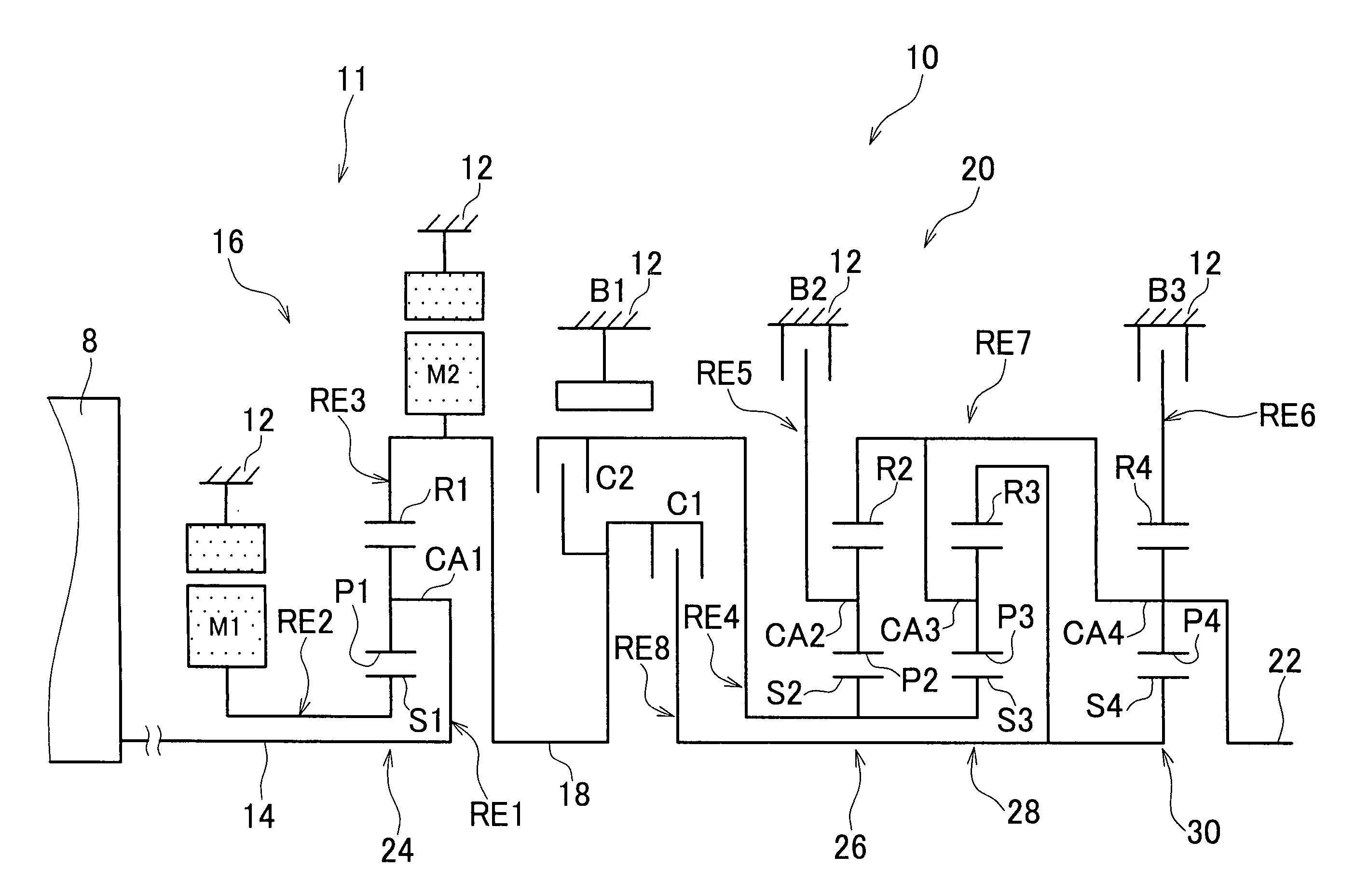
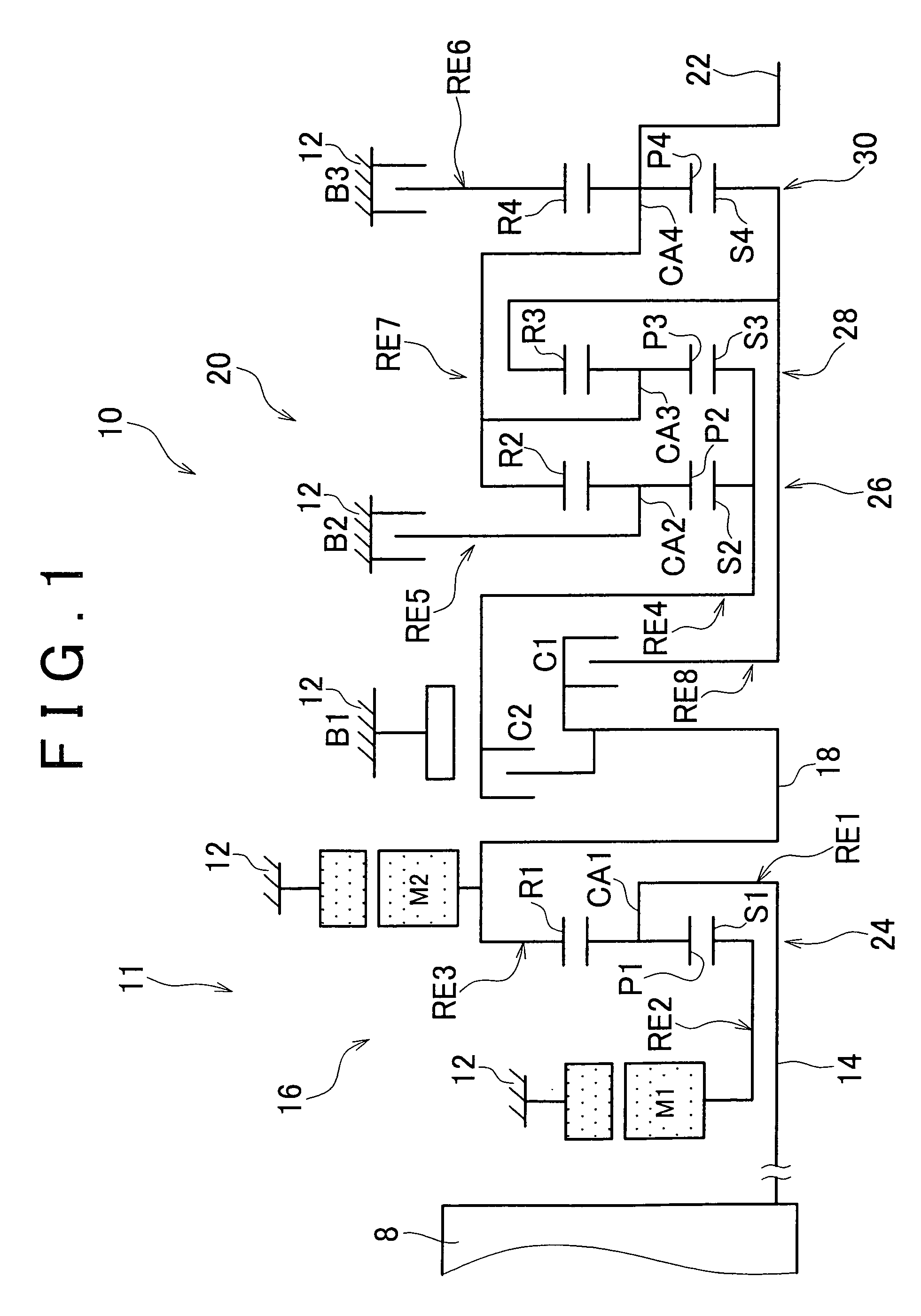
[0036]In the transmission mechanism 10 of the first embodiment, the engine 8 and the differential motion portion 11 are directly coupled. Being directly coupled herein means being linked without the intervention of a fluid type transmission device, such as a torque converter, a fluid coupling, etc.; for example, the aforementioned linkage via the pulsation absorbing damper or the like is included in this direct coupling. Incidentally, the transmission mechanism 10 is constructed symmetrically about its axis, and in the skeleton diagram of FIG. 1, the lower half thereof is omitted from illustration.

[0037]The differential motion portion 11 includes a first electric motor M1, a power distribution mechanism 16 as a differential mechanism which is a mechanical mechanism that mechanically distributes the output of the engine 8 (hereinafter, referred to as “the engine output”) input to the input shaft 14 and which distributes the engine output to the first electric motor M1 and the transmi...

second embodiment

[0124]Concretely, the engagement process alteration device 88 delays the execution of the switch of the transmission mechanism 10 from the non-driving state to the driving state, that is, the engagement of the friction engagement device or devices (e.g., the clutch C1 and the brake B3 in the case where the first speed step in the automatic ratio shift portion 20 is established in the N→D garage shift), from the ordinary timing of the execution. Specifically, in the example shown in FIG. 14, the driver's operation of the shift operation device 50 and the start of the engagement of the friction engagement device occur substantially simultaneously at the time t31. However, according to the engagement process alteration device 88 of the second embodiment, the engagement of the friction engagement device is started after a predetermined time elapses following the driver's operation of the shift operation device 50. The predetermined time herein is, for example, in the case where the engi...


PUM


Abstract

A control device for a vehicle power transmission device including an electrical differential motion portion in which a differential state between input shaft rotation speed and output shaft rotation speed is controlled through control of the operation state of an electric motor linked to a rotating element of a differential motion portion, and a power connection-disconnection device constituting a portion of a power transmission path, includes a controller that lessens a transmission capacity of the power connection-disconnection device if during a switch of the state of the vehicle power transmission device from a non-driving state to a driving state, a change in input torque to the vehicle power transmission device occurs, in comparison with when the change in the input torque does not occur. Therefore, the control device reduces the shift shock when the vehicle power transmission device is switched from the non-driving to the driving state.

Description

INCORPORATION BY REFERENCE[0001]The disclosure of Japanese Patent Application No. 2007-163174 filed on Jun. 20, 2007, including the specification, drawings and abstract is incorporated herein by reference in its entirety.BACKGROUND OF THE INVENTION[0002]1. Field of the Invention[0003]The invention relates to a vehicle power transmission device and, more particularly, to a technology of reducing the shock that occurs when the vehicle power transmission device is switched from a non-driving state to a driving state.[0004]2. Description of the Related Art[0005]There is a known vehicle power transmission device that includes an electrical differential motion portion in which the differential state between the input shaft rotation speed and the output shaft rotation speed is controlled through the control of the operation state of an electric motor linked to a rotating element of a differential motion portion, and a power connection-disconnection device that constitutes a portion of a po...

Claims


Application Information

Patent Timeline
Patent Type & Authority Patents(United States)
IPC IPC(8): B60W10/08B60K6/445B60K6/547B60K17/04B60L50/16B60W10/02B60W20/00F16D48/02
CPCB60K6/445B60K6/547B60W10/06B60W10/08B60W10/115B60W20/00F16H61/0437B60K6/365B60K1/02Y10T477/26B60L2240/421B60L2240/441B60L2240/445B60L2240/485B60L2240/486B60W2510/0638B60W2510/0676B60W2510/068B60W2510/0685B60W2510/081B60W2510/107B60W2510/244B60W2510/246B60W2520/10B60W2520/105B60W2520/28B60W2530/10B60W2540/10B60W2540/12B60W2540/16F16H3/728F16H2037/0873F16H2061/0485F16H2061/0488F16H2200/0043F16H2200/2012F16H2200/2043F16H2312/02F16H2312/14Y02T10/6286Y02T10/642Y02T10/6239B60Y2400/435Y10T477/23Y02T10/62Y02T10/64B60W20/10
Inventor MATSUBARA, TOORUTABATA, ATSUSHIKAIFUKU, MASAKAZU
Owner TOYOTA JIDOSHA KK
Why Eureka
Try Eureka