Remote monitoring and control system

a monitoring and control system technology, applied in the direction of signalling systems, electric signalling details, instruments, etc., can solve the problems of high labor intensity and high cost of systems, such as installation, maintenance and/or operation, and many systems can be highly unreliabl

Active Publication Date: 2010-11-02
SUNRISE TECH
View PDF25 Cites 436 Cited by
  • Summary
  • Abstract
  • Description
  • Claims
  • Application Information

AI Technical Summary

Problems solved by technology

In many cases, however, the systems are labor-intensive and very expensive either in equipment cost, installation, maintenance, and / or operation.
Furthermore, many systems can be highly unreliable and are subject to difficulties caused by weather, system aging, environmental factors such as vandalism and accidents, and intentional interference with operation by various parties.
There are, however, numerous problems with hardwired systems, including installation expenses and vulnerability to tampering.
Wireless communication links, however, typically possess critical difficulties.
Typically, wireless communication links are relatively expensive and generally too expensive to be used in many typical remote monitoring and control systems.
This expense factor goes up considerably as the distance between the elements of the wireless communication link rises and as bandwidth requirements rise.
Furthermore, typically, wireless communication links have relatively high power requirements that are too great to be used in many typical remote monitoring and control systems.
In many cases, the use of local domestic power is impractical because of installation issues and reliability issues.
Typical power-hungry devices have power requirements that are impractical for battery power and even battery backup.

Method used


Image

  • Remote monitoring and control system
  • Remote monitoring and control system
  • Remote monitoring and control system

Examples


Embodiment Construction

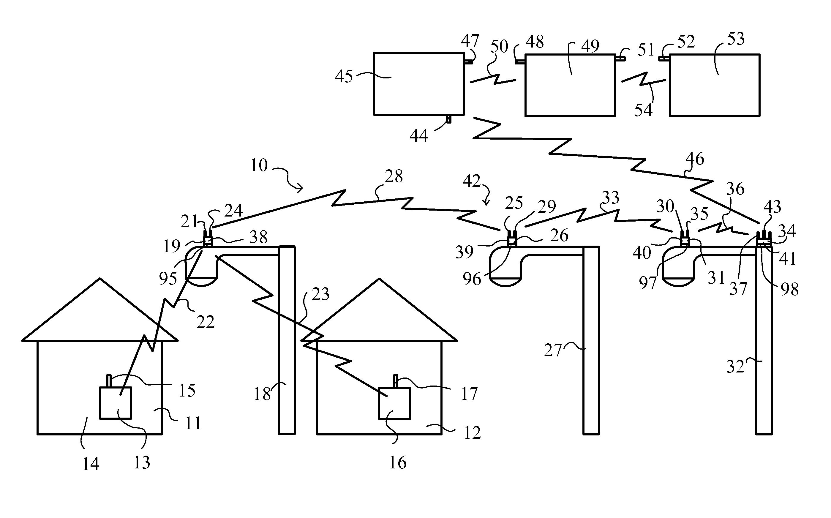
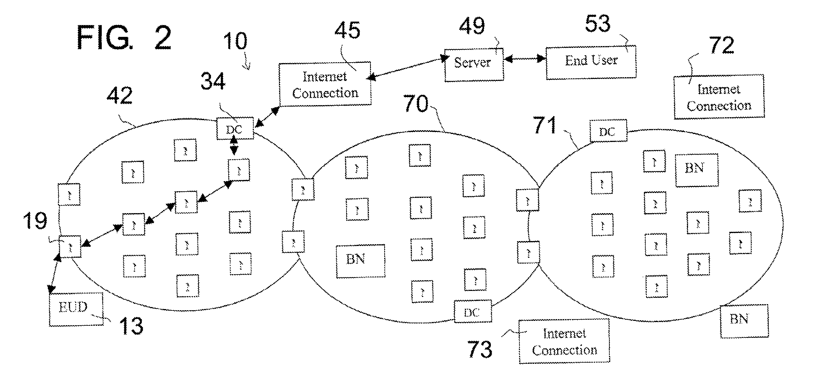
[0025]This invention is a combination and interconnection of two existing technologies; mesh networks, and low-power, low-cost transceivers. The invention allows a person (an “end user” such as a city electrical worker) to monitor and / or control certain events (such as municipal electrical use) that are occurring in a remote location (such as any particular house), with an end user device (such as a domestic electrical use meter and associated communications device).

[0026]One base technology is a mesh network, a network of communication nodes distributed around a geographical area and capable of communicating with one another. In some mesh networks, the network is capable of communicating downward to lower-level communication devices within the geographic area. These lower-level devices are capable of communicating with one or more nodes of the mesh network. The mesh network is also capable of communicating upward to a network that extends beyond the geographical area of the mesh ne...


PUM


Abstract

A communication system that provides communication of information between an end user device and a remote end user. The system includes a communication node mounted on the upper part of a utility pole, and drawing its power from the utility pole through a standard NEMA Locking 3 Pole Receptacle, and adapted to communicate with a nearby user device using the low-power communication protocol, such as the ZigBee protocol (ANSI IEEE 802.15.4) or Radio Frequency Identification Device (RFID) technology, and also adapted to communicate with a neighborhood mesh network of nodes mounted on utility poles. The neighborhood mesh network is capable of communicating, through a regional computer network, with the remote end user.

Description

CROSS-REFERENCE TO RELATED APPLICATIONS[0001]This application claims the benefit under 35 U.S.C. §119(e) of U.S. Provisional Application No. 60 / 815,551 filed Jun. 21, 2006, which is hereby incorporated by reference.STATEMENT REGARDING FEDERALLY SPONSORED RESEARCH OR DEVELOPMENT[0002]This invention has been created without the sponsorship or funding of any federally sponsored research or development program.FIELD OF THE INVENTION[0003]This invention is a system for remote monitoring and control of a target zone by an end user.BACKGROUND OF THE INVENTION[0004]This invention is a system for monitoring and controlling parameters, such as air conditioning, water heating, unauthorized intrusion, electric use, water use, or gas use within a target sites such as a building, by a remote end user, who might be an operator at a fuel delivery dispatch facility, or at an intrusion monitoring center, or in a municipal water headquarters. Many systems have been developed to provide data communicat...

Claims


Application Information

Patent Timeline
Patent Type & Authority Patents(United States)
IPC IPC(8): G08B1/08
CPCG08B13/1966G08B25/009
Inventor SPILLMAN, VANCE P.ROSENQUIST, CRAIG H.HALL, JAMES G.WALKER, DANIEL C.
Owner SUNRISE TECH
Why Eureka
Try Eureka