
Lens module

a technology of lens module and lens module, applied in the field of lens module, can solve the problems of still having some drawbacks, affecting the reduction of the overall size of the lens module, etc., and achieve the effect of convenient combined

Inactive Publication Date: 2010-11-02
SKINA OPTICAL
View PDF1 Cites 11 Cited by
  • Summary
  • Abstract
  • Description
  • Claims
  • Application Information

AI Technical Summary

Benefits of technology

"The present invention provides a lens module with a simplified magnet yoke and a lower coupling element that securely and conveniently combine together. The lens module includes an upper coupling element, a spring, a magnet yoke, a plurality of magnets, a coil, a lens holder, and a lower coupling element. The upper coupling element has multiple engaging posts, and the lower coupling element includes multiple engaging grooves and concave structures that mate with the engaging posts and magnets for easy assembly. The lens module is designed to have a simplified structure and is convenient for use in various applications."

Problems solved by technology

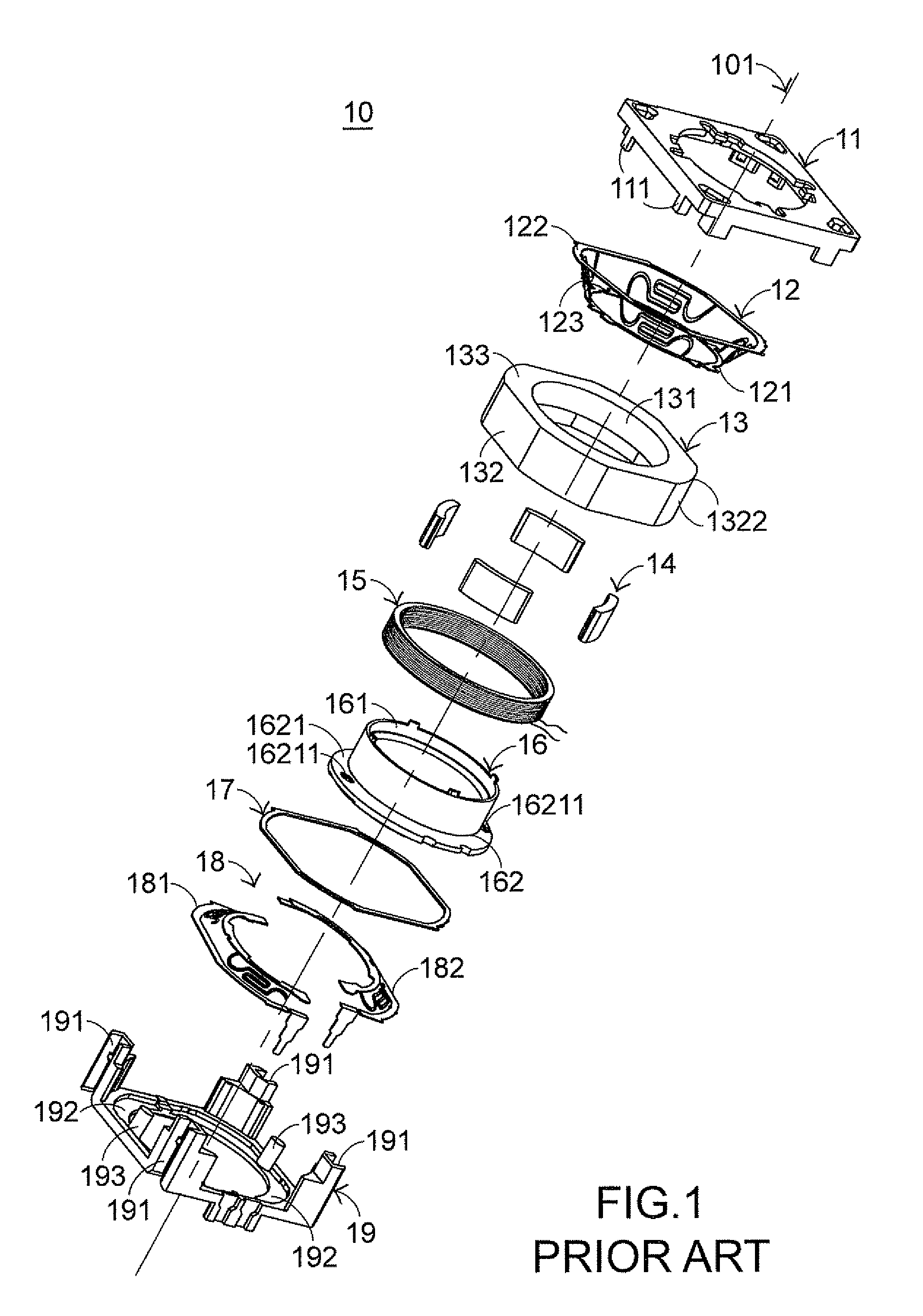
The lens module having the auto focus function or the auto macro function according to the conventional techniques, however, still has some drawbacks.
In other words, since the thickness of the annular flange 1621 of the lens holder 16 fails to be considerably reduced, it is detrimental to reduction of the overall size of the lens module.

Method used


Image

  • Lens module
  • Lens module
  • Lens module

Examples


Embodiment Construction

[0059]It is to be noted that the following descriptions of preferred embodiments of this invention are presented herein for purpose of illustration and description only. It is not intended to be exhaustive or to be limited to the precise form disclosed.

[0060]The present invention relates to a lens module that is driven by a voice coil motor. The lens module of the present invention has an auto focus function or an auto macro function.

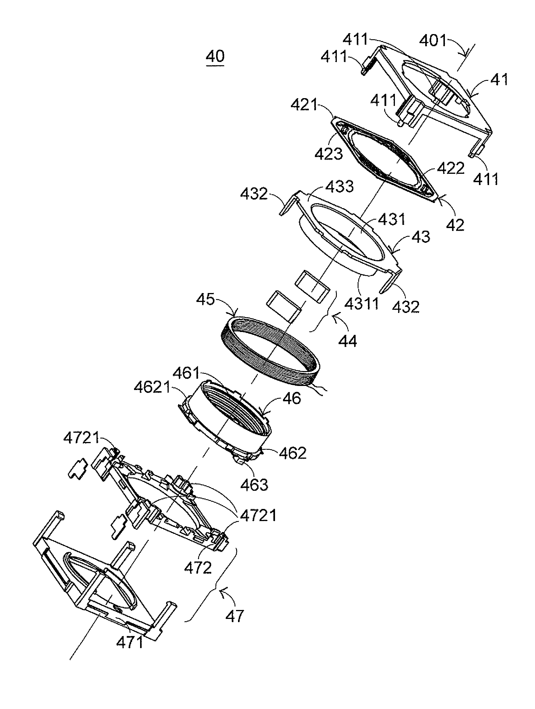
[0061]FIG. 5 is a schematic exploded view illustrating a lens module that is driven by a voice coil motor according to a preferred embodiment of the present invention. The lens module 40 principally comprises an upper coupling element 41, a spring 42, a magnet yoke 43, several magnets 44, a coil 45, a lens holder 46, and a lower coupling element 47. The lower coupling element 47 includes a lower case 471 and a base 472.

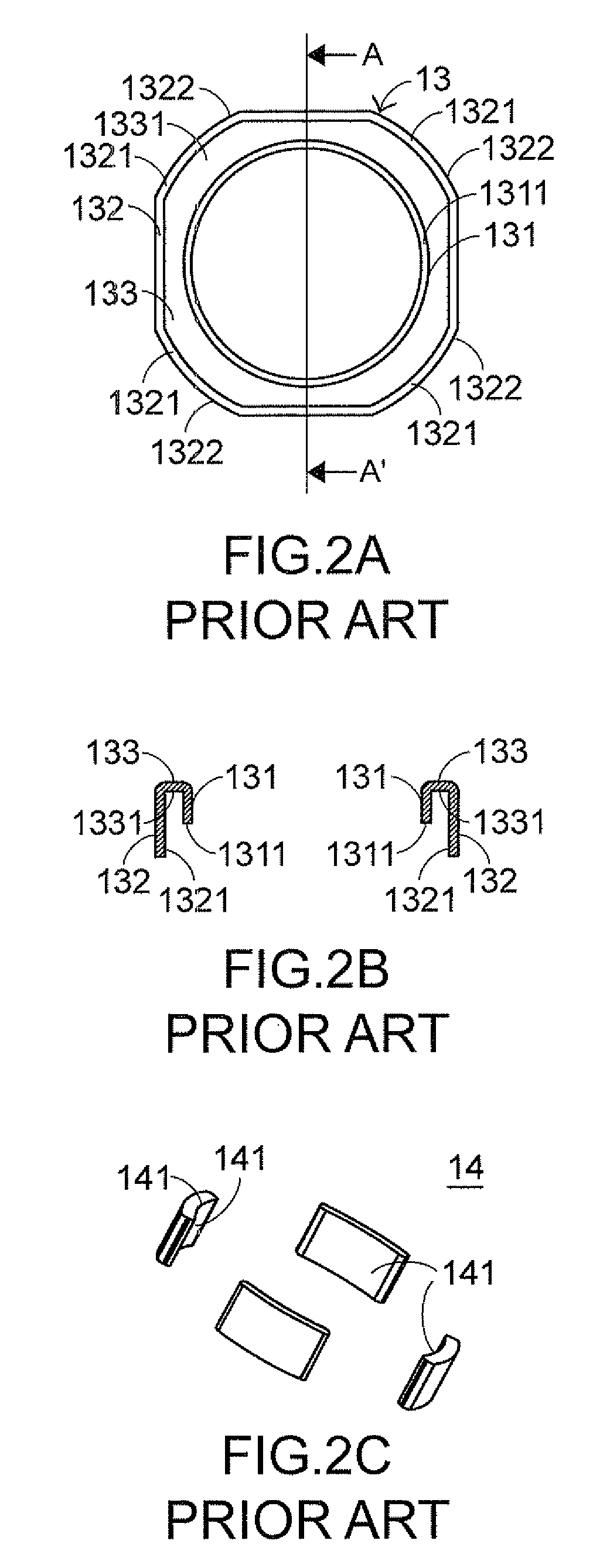
[0062]FIG. 7A is a schematic top view illustrating the magnet yoke of the lens module shown in FIG. 5. FIG. 7B is a schematic rear view ...


PUM


Abstract

A lens module includes an upper coupling element, a spring, a magnet yoke, a plurality of magnets, a coil, a lens holder and a lower coupling element. The magnet yoke is disposed under the spring and has a cylindrical inner wall, multiple extension slices and a top wall. The top wall is outwardly extended from an upper edge of the cylindrical inner wall. The extension slices are downwardly and axially extended from a periphery of the top wall and circumferentially arranged on the top wall at regular intervals. The magnets are attached on inner surfaces of respective extension slices of the magnet yoke. At least two raised structures are circumferentially arranged on the lower periphery of the lens holder. The lower coupling element includes at least two concave structures mating with the raised structures.

Description

CROSS-REFERENCE TO RELATED APPLICATION[0001]This application claims priority under 35 U.S.C. §119 to Taiwan Patent Application No. 097145623, filed on Nov. 26, 2008, in the Taiwan Intellectual Property Office, the entire contents of which are hereby incorporated by reference.FIELD OF THE INVENTION[0002]The present invention relates to a lens module, and more particularly to a lens module that is driven by a voice coil motor.BACKGROUND OF THE INVENTION[0003]As known, a lens module that is driven by a voice coil motor (VCM) is advantageous for reducing the overall size of the lens module and lowering the product price. Nowadays, the voice coil motor is applied to the lens module having an auto focus function and / or an auto macro function. The auto focus function enables the optical system to obtain correct focus on a subject without requiring the operator to manually adjust focus. The auto macro function allows for close-up shots when the distant from the subject is very short.[0004]F...

Claims


Application Information

Patent Timeline
Patent Type & Authority Patents(United States)
IPC IPC(8): G02B7/02
CPCG02B7/08
Inventor CHEN, LIANG-JENGWU, CHEN-HUNG
Owner SKINA OPTICAL
Learn More