
Communication node, wireless communication system and data relay method

a communication node and wireless communication technology, applied in the field of wireless communication, can solve the problems of limited communication capacity of relay system, interference, largely reduced communication capacity, etc., and achieve the effect of improving the communication capacity in the multi-hop scheme and increasing the communication capacity

Inactive Publication Date: 2010-11-02
NTT DOCOMO INC
View PDF5 Cites 21 Cited by
  • Summary
  • Abstract
  • Description
  • Claims
  • Application Information

AI Technical Summary

Benefits of technology

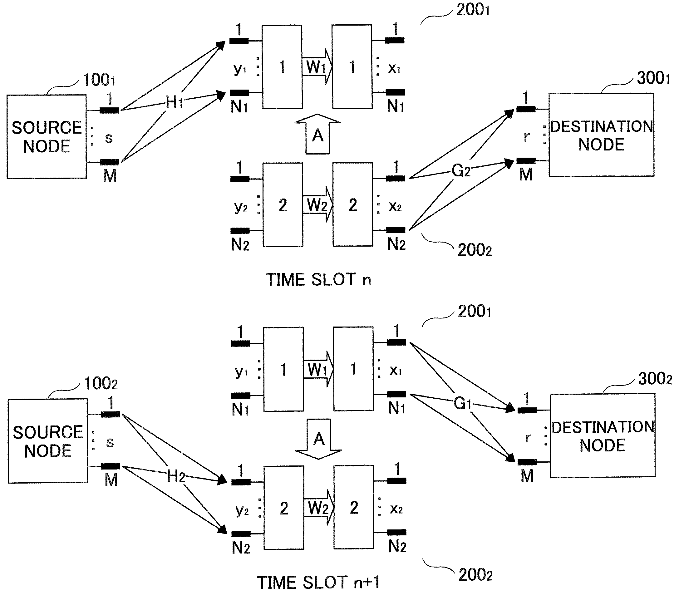
[0027]An object of the present invention is to provide a relay node, a destination node and a communication method for improving the communication capacity in the multi-hop scheme or the relay scheme using the MIMO scheme.
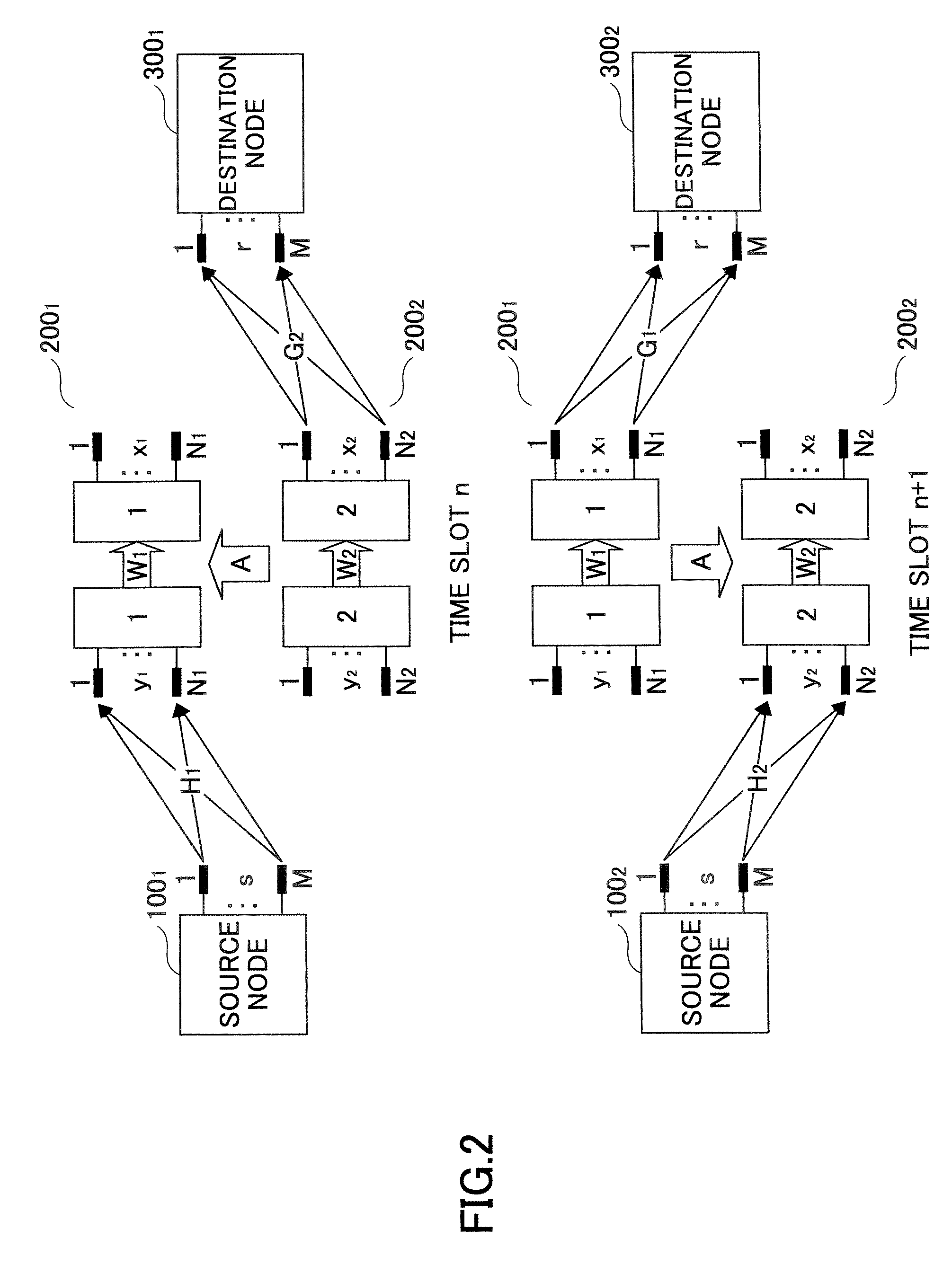
[0048]According to the present invention, interference between relay nodes that send and receive signals can be cancels so that a relay node for receiving and a relay node for transmitting can coexist. Therefore, the communication capacity can be increased compared with the conventional relay method.
[0049]According to embodiments of the present invention, a communication node, a wireless communication system and a communication method for improving the communication capacity in the multi-hop scheme or the relay scheme using the MIMO scheme can be realized.

Problems solved by technology

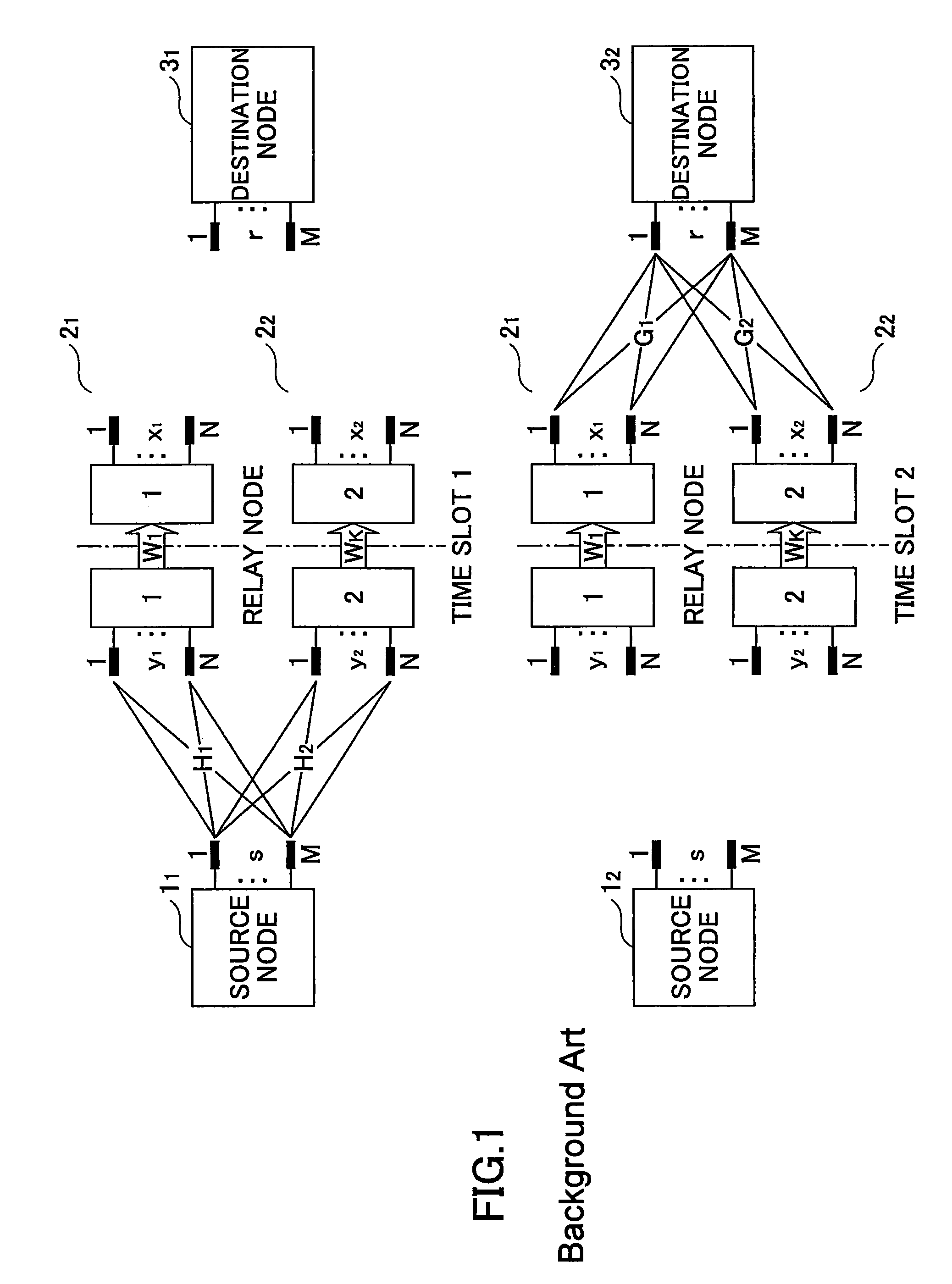
However, communication capacity is largely reduced due to the time division scheme so that the communication capacity of the relay system is limited.
When transmission and receiving are performed simultaneously in each relay node, a signal sent from a relay node is received by another relay node so that interference occurs.
As a result, the relay node cannot properly receive a signal sent from the source node 1.
Therefore, the communication capacity is limited as a whole.
However, as represented by the multiplication of “½” in the equation (4) representing the communication capacity, there is a problem in that the communication capacity is reduced.

Method used


Image

  • Communication node, wireless communication system and data relay method
  • Communication node, wireless communication system and data relay method
  • Communication node, wireless communication system and data relay method

Examples


second embodiment

[0132]Next, a wireless communication system of the present invention is described.

[0133]In the wireless communication system in this embodiment, the relay node 200 sends a received signal as it is. In addition, in the wireless communication system in this embodiment, a part of relay nodes perform receiving processes, and at the same time, other relay nodes perform sending processes.

[0134]In this situation, the destination node 300 of this embodiment cancels interference occurring between the relay nodes.

[0135]The configuration of the wireless communication system of this embodiment is the same as that of the wireless communication system described with reference to FIG. 2.

[0136]A configuration of the destination node 300 of this embodiment is described with reference to FIG. 5. The destination node 300 is a communication node that receives a signal sent from the source node via the relay node.

[0137]The destination node 300 includes a transmit signal estimation unit 302 that receives...

first embodiment

[0161]Different from the first embodiment, in the wireless communication system of this embodiment, there is no limitation for the numbers N and M of the antennas.

third embodiment

[0162]Next, a wireless communication system of a third embodiment is described.

[0163]In the wireless communication system of this embodiment, each relay node performs signal detection so as to cancel interference between relay nodes. Accordingly, the signal from which interference is canceled in the relay nodes can be sent without performing causing interference suppression. In addition, it is not necessary that the destination node 300 performs interference cancellation between relay nodes.

[0164]The configuration of the wireless communication system of this embodiment is the same as that shown in FIG. 2.

[0165]A configuration of the relay node 200 of this embodiment is described with reference to FIG. 7. The relay node 200 is a communication node for relaying a signal between the source node and the destination node.

[0166]The relay node 200 includes an interference canceling unit 202 that receives a receive signal, a signal detection unit 210 that receives an output signal of the in...


PUM


Abstract

A communication node for relaying a signal between a source node and a destination node is disclosed. The communication node includes: a relay signal generation unit configured to generate a transmit signal by reducing, from a receive signal, an interference signal from another communication node and performing a process such that the transmit signal is not received as an interference signal by another communication node.

Description

BACKGROUND OF THE INVENTION[0001]1. Field of the Invention[0002]The present invention generally relates to a wireless communication technical field. More particularly, the present invention relates to a communication node, a wireless communicant system and a data relay method that use the multi-hop scheme, the relay scheme and the MIMO (Multi-Input Multi-Output) scheme.[0003]2. Description of the Related Art[0004]In a conventional relay method, signal transmission and signal receiving are performed in a time division manner such that a transmit signal and a receive signal does not interfere with each other at the relay node. However, communication capacity is largely reduced due to the time division scheme so that the communication capacity of the relay system is limited.[0005]The conventional relay method is described with reference to FIG. 1. The reason why the communication capacity is largely limited is described in the following.[0006]In FIG. 1, following parameters are defined...

Claims


Application Information

Patent Timeline
Patent Type & Authority Patents(United States)
IPC IPC(8): H04J1/12H04J99/00
CPCH04B7/15585H04B7/2606
Inventor SHI, HUIASAI, TAKAHIROYOSHINO, HITOSHI
Owner NTT DOCOMO INC
Learn More