Coaxial connector with telescoping center conductor mechanism

a center conductor and coaxial cable technology, applied in the direction of line/current collector details, coupling device connections, electrical apparatus, etc., can solve the problems of no means to ensure, loss, and the center conductor of the coaxial cable is blocked from a user's view, and achieves the effect of simple and inexpensiv

Active Publication Date: 2010-11-09
PPC BROADBAND INC
View PDF17 Cites 25 Cited by
  • Summary
  • Abstract
  • Description
  • Claims
  • Application Information

AI Technical Summary

Benefits of technology

[0014]The connector further comprises a sabot that moves with the contact assembly within the body preferably in a telescoping fashion enabling a greater distance of axial displacement. The said guide of the contact assembly provides a means to prevent appreciable backward movement of the contact assembly and cable core after the contact assembly and cable core have been moved fully forward within the connector.
[0015]In a preferred embodiment, the present invention can provide a coaxial connector that is more “installer friendly” and incorporates a positive visual indication that the connector is properly installed on a coaxial cable.
[0016]In a preferred embodiment, the present invention can provide a connector that has a contact that does not reside proximate the front end of the connector prior to use.
[0017]In a preferred embodiment, the present invention can provide a connector that provides a user with a view of an opening of the contact assembly into which the center conductor of a coaxial cable is to be inserted, while the coaxial cable is being inserted into the connector during attachment.
[0019]In a preferred embodiment, the present invention can provide a connector with a relatively long center contact arrangement that can guide said contact arrangement.
[0020]In a preferred embodiment, the present invention can provide a connector that contains a simple and inexpensive means to prevent the assembled contact assembly and cable core from being forced appreciably backward by a load applied to the front end of the contact during mating with corresponding connectors.

Problems solved by technology

Disadvantageously, most known connectors require “blind entry” of the coaxial cable into the connector, meaning that a small opening in the connector into which it is necessary to insert the center conductor of the coaxial cable becomes blocked from a user's view by a dielectric or jacket of the coaxial cable.
The dielectric or jacket blocks the user's view of the small opening primarily because the small opening is disadvantageously recessed too deeply in the connector.
Such known connectors provide no means to ensure that the dielectric, or foam core, of the coaxial cable is properly centered within the connector during insertion of the coaxial cable into the connector.
Many known connectors utilize separate or loose components that must be manipulated during installation, and, therefore, are subject to loss.
The loose pin is subject to loss.
Using the center conductor of the coaxial cable to push out the pin does not work well, if at all, when the center conductor is a small gauge wire.
Often times, said connectors are long in overall length due to application and design constraints and require a relatively long center contact arrangement.

Method used


Image

  • Coaxial connector with telescoping center conductor mechanism
  • Coaxial connector with telescoping center conductor mechanism
  • Coaxial connector with telescoping center conductor mechanism

Examples


Embodiment Construction

[0042]Additional features and advantages of the invention will be set forth in the detailed description which follows and will be apparent to those skilled in the art from the description or recognized by practicing the invention as described in the following description together with the claims and appended drawings.

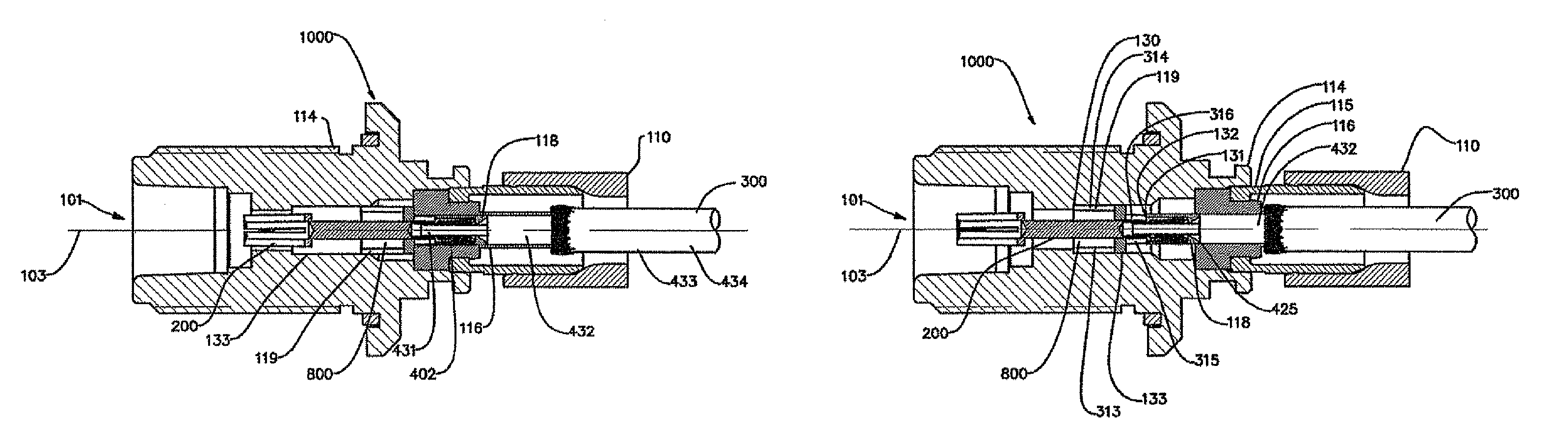
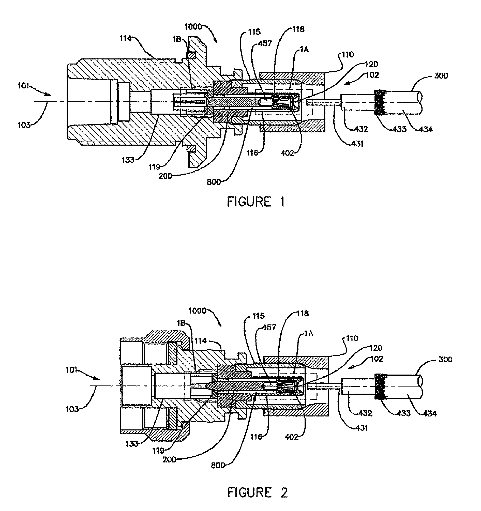
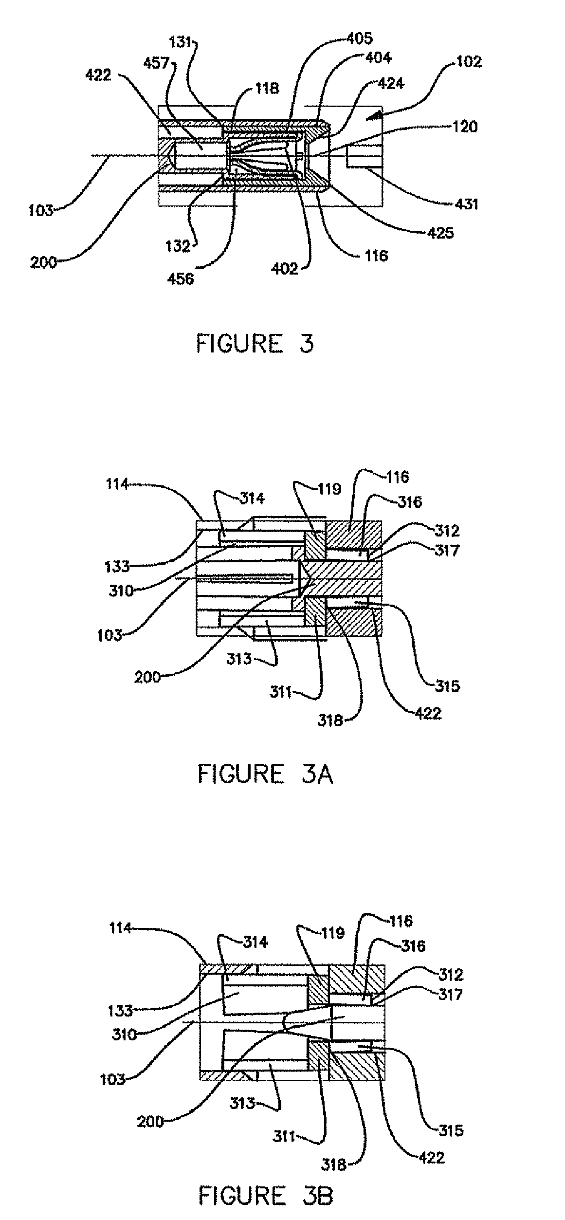
[0043]As used herein, the term “contact assembly” refers to an assembly that is longitudinally movable within a connector and contacts a center conductor of a coaxial cable at one end and has a male or female contact at the other end, wherein the male or female contact can be used to interface or mate with corresponding connectors. In at least one preferred embodiment, the contact assembly includes a guide at one end for electrically and mechanically contacting the center conductor of a coaxial cable. The guide is preferably a female component into which the center conductor of the coaxial cable is inserted, thereby establishing electrical and mechanical contact between...


PUM


Abstract

A connector having a front end for attachment to a terminal and a back end for attachment to a coaxial cable includes a body, a post mounted within the body; and a contact assembly movably mounted within the post and body. The contact assembly includes a guide, a contact mounted to the guide, and preferably a clip mounted to the contact for making electrical and mechanical connection with the center conductor of the coaxial cable and a sabot. The contact assembly moves longitudinally toward the front end of the connector, such that the front end of the contact moves from a first position completely within the body to a second position proximate the connector interface, as the connector receives the coaxial cable. Preferably, the guide has an opening for the center conductor, which is viewable to a user during attachment until the center conductor enters the opening. The sabot moves with the contact assembly in a telescoping fashion enabling a greater distance of axial displacement. In addition, the contact assembly preferably contains a means to prevent the cable from being forced backward after installation.

Description

CROSS-REFERENCE TO RELATED APPLICATIONS[0001]This application claims the benefit of, and priority to U.S. Provisional Patent Application No. 61 / 001,182 filed on Oct. 31, 2007 entitled, “Coaxial Connector with Telescoping Center Conductor Mechanism”, the content of which is relied upon and incorporated herein by reference in its entirety.BACKGROUND OF THE INVENTION[0002]1. Field of the Invention[0003]This invention relates generally to coaxial cable connectors, and more particularly to coaxial cable connectors capable of being connected to a terminal.[0004]2. Technical Background[0005]Coaxial cable connectors, such as axially-compressible Type N connectors, are used to attach a coaxial cable to another object, such as an appliance or junction, having a terminal adapted to engage the connector. After an end of the coaxial cable is trimmed using one of several known cable preparation techniques, the trimmed end of the coaxial cable is inserted into a back end of the connector. Then, th...

Claims


Application Information

Patent Timeline
Patent Type & Authority Patents(United States)
IPC IPC(8): H01R9/05
CPCH01R9/0524H01R13/5812H01R43/00
Inventor BURRIS, DONALD ANDREWCLAUSEN, JAN MICHAEL
Owner PPC BROADBAND INC
Why Eureka
Try Eureka