Frame to support pull-out and rotating racks for cabinets

Inactive Publication Date: 2010-11-16
COMPAGNUCCI
View PDF9 Cites 21 Cited by
  • Summary
  • Abstract
  • Description
  • Claims
  • Application Information

AI Technical Summary

Benefits of technology

[0014]The main purpose of the present invention is to provide an improved frame used to support pull-out and rotating racks for cabinets, which comprises guiding means able

Problems solved by technology

The first problem consists in the fact that, when pulling-out the rack, the rack can accidentally rotate before the forward travel is completed, thus making the shelves of the rack touch and rub the sides of the cabinet.
The second inconvenience occurs during the installation of the rack, when the door must be regulated to perfectly touch the

Method used


Image

  • Frame to support pull-out and rotating racks for cabinets
  • Frame to support pull-out and rotating racks for cabinets
  • Frame to support pull-out and rotating racks for cabinets

Examples


Embodiment Construction

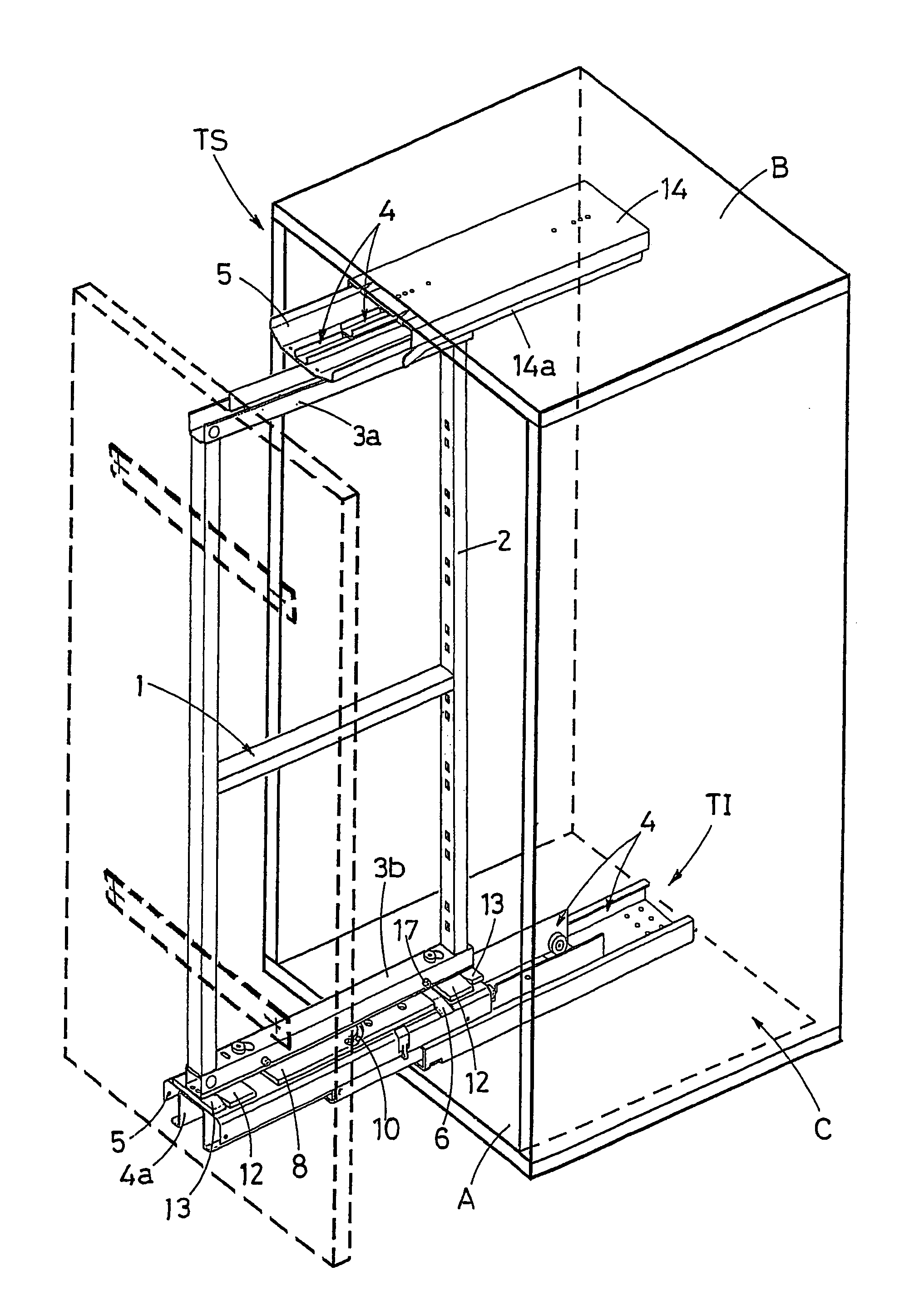
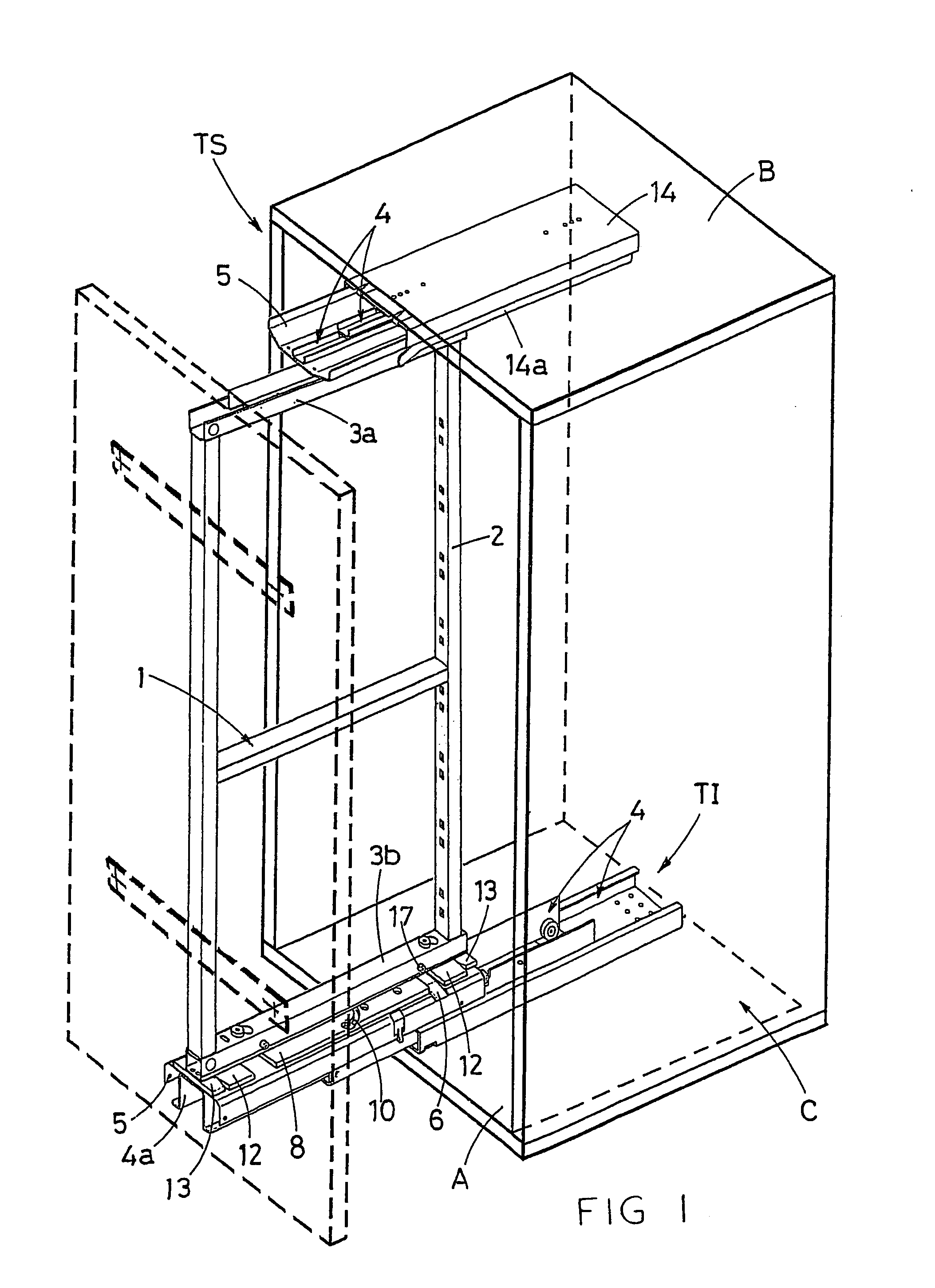
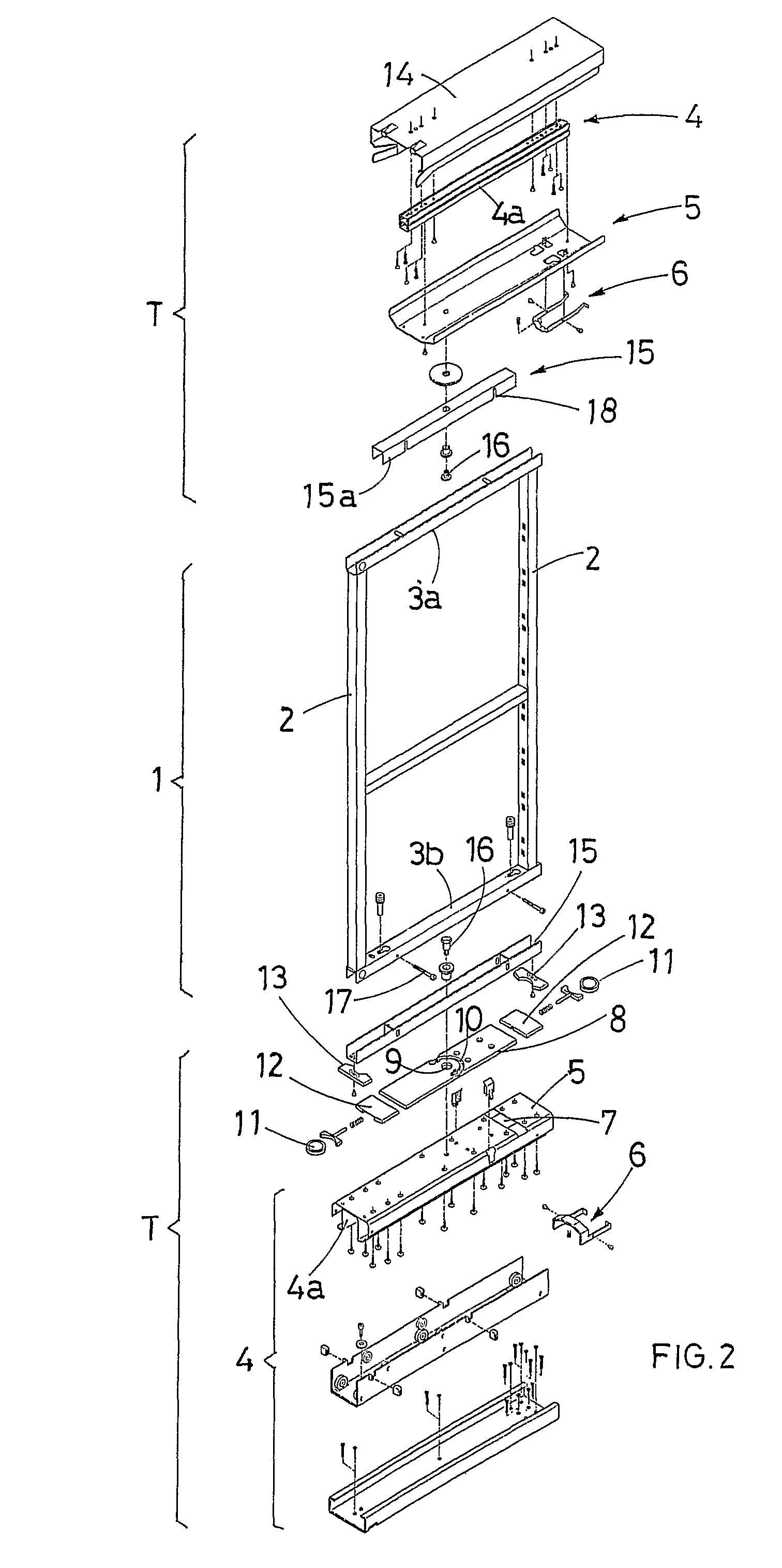
[0030]With reference to the aforementioned figures, the improved frame (T) is designed to support a rack (1) that slides and rotates around a vertical axis, which is composed of a bearing rectangular structure formed of two uprights (2) connected by two crosspieces, in upper (3a) and lower (3b) position, respectively coupled to the sliding rod (4a) of two telescopic guides (4) mounted on the bottom (A) and top (B) of the cabinet (C) where the rack (1) is to be contained.

[0031]The frame (T) is composed of a lower semi-frame (TI) fixed on the bottom (A) and an upper semi-frame (TS) fixed to the top (B) of the cabinet.

[0032]In both semi-frames (TI and TS) the frame (T) comprises a special cover (5) designed to be fixed to the sliding rod (4a) of the telescopic guides (4) to support the mechanisms used to guarantee the correct, safe movement of the rack, which are already known and disclosed in the aforementioned application for utility model MC 2004 U000004.

[0033]More precisely, the sa...


PUM


Abstract

An improved frame to support pull-out and rotating racks for cabinets. The frame has a telescopic guide with a sliding end. The rack is prevented from accidentally rotating during pull-out.

Description

BACKGROUND OF THE INVENTION[0001]The present application refers to an improved frame used to support pull-out and rotating racks, such as the ones commonly used in modern modular kitchen cabinets to support a series of shelves or baskets for food storage purposes.[0002]A frame for racks of this type is disclosed in the Italian application for utility model MC 2004 U000004 filed by the same applicant.[0003]The said application discloses a frame used to support racks that slide and rotate around a vertical axis, composed of a bearing rectangular structure formed of two uprights connected by two crosspieces, namely an upper and a lower crosspiece, respectively coupled to the sliding rod of two telescopic guides mounted on the bottom and top of the cabinet where the rack is to be contained.[0004]The crosspieces are fixed to the sliding rods by means of vertical coaxial pins that allow the rack to rotate with respect to the sliding rods, which in turn allow the rack to be pulled out of t...

Claims


Application Information

Patent Timeline
IPC IPC(8): A47B88/04A47B88/48
CPCA47B88/0485A47B2088/0488A47B2220/0011A47B88/42A47B2088/421
Inventor COMPAGNUCCI, ROSSANO
Owner COMPAGNUCCI
Why Eureka
Try Eureka