Suspension cable of space cable rope structure

A sling and cable technology, applied in suspension bridges, bridge parts, bridge forms, etc., can solve problems such as inability to adapt to the construction of suspension bridges, and achieve the effect of facilitating sling tension, adjustable sling length, and easy adjustment.

Active Publication Date: 2009-01-21
LIUZHOU OVM MASCH CO LTD +3
View PDF0 Cites 18 Cited by
  • Summary
  • Abstract
  • Description
  • Claims
  • Application Information

AI Technical Summary

Problems solved by technology

[0003] The technical problem to be solved by the present invention is to provide a suspension bridge sling that can adapt to the space cable structure. During the construction process of the sling from the empty cable state to the bridge state, the sling body can rotate at a larger angle and It can be moved, stretched, and adjusted in length to solve the problem that the structure of the existing sling cannot adapt to the construction of a suspension bridge with a space cable structure

Method used


Image

  • Suspension cable of space cable rope structure
  • Suspension cable of space cable rope structure
  • Suspension cable of space cable rope structure

Examples


Embodiment 1

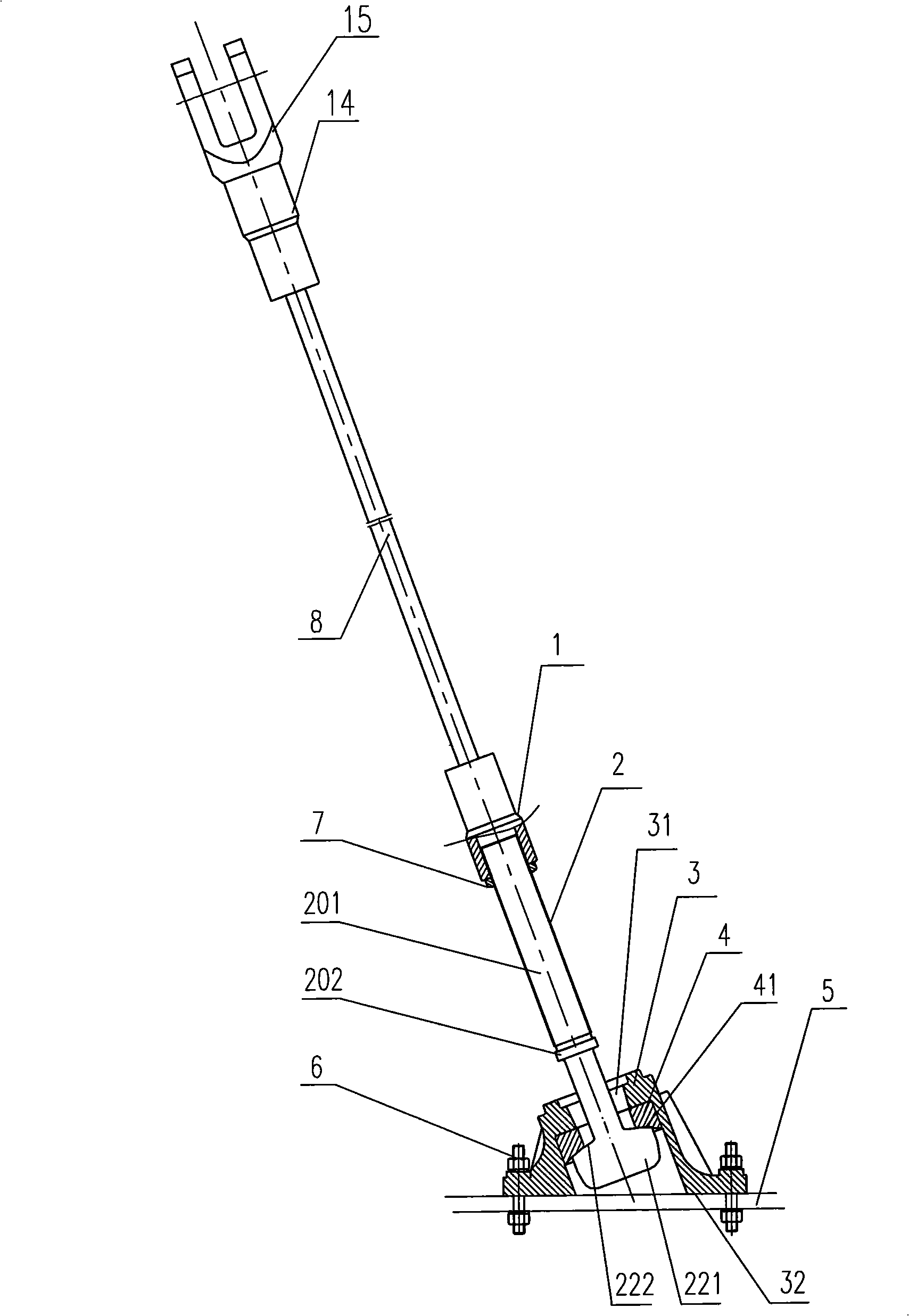
[0025] A sling of a space cable structure, comprising a sling body 8, an upper anchorage 14 connected to the upper end of the sling body 8, and a lower anchoring device connected to the lower end of the sling body 8, the lower anchoring device comprising The lower end anchorage, the connecting rod 2, the base 3 and the rotating pair between the connecting rod 2 and the base 3, the connecting rod 2 is a whole rod, which is a threaded long rod with a cylindrical head 221 at the lower end and an external thread at the upper end. The thread end of the long threaded rod is provided with a tension step 202; the base 3 is a tower with a step hole 31, a small upper end and a large bottom end, and its bottom end face 32 is an inclined surface; the rotating pair It is a ring-shaped inner spherical support 4 with one end being a plane and the other end being an inner spherical surface 41. The upper end of the connecting rod 2—the threaded rod end 201 passes through the step hole 31 of the...

Embodiment 2

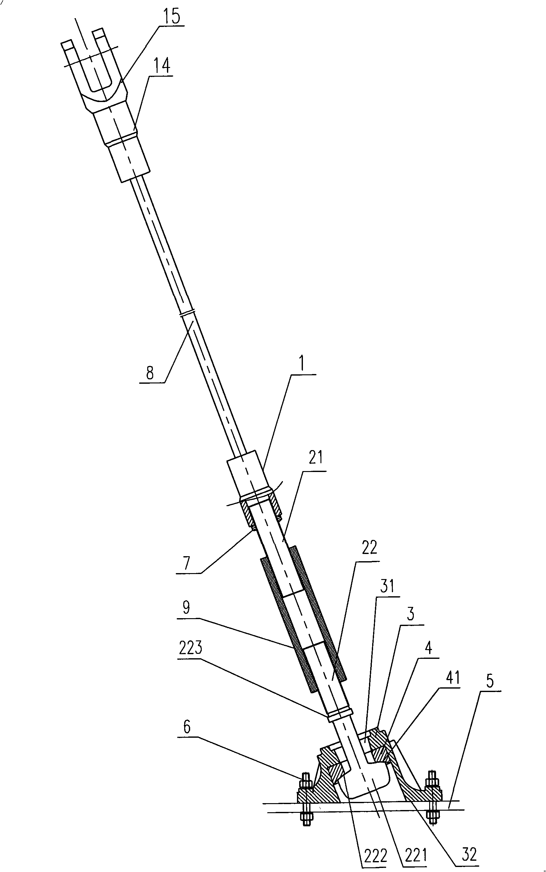
[0029] A sling with a space cable structure, its basic structure is the same as that of Embodiment 1, the difference is that the connecting rod 2 is composed of two parts: a separate threaded connecting rod 21 and a cylindrical head connecting rod 22, and the threaded connecting rod 21 is a connecting rod with external threads at both ends, and a cylindrical head connecting rod 22 is a connecting rod with external threads at one end and a cylindrical head 221 at the other end. The threaded connecting rod 21 and the cylindrical head connecting rod 22 pass through The connecting sleeve 9 connection of the internally threaded through hole (see figure 2 ).

[0030] As a modification of this embodiment, the threaded connecting rod 21 can also be a connecting rod with an external thread at one end and a connecting sleeve 9 with an internally threaded hole at the other end. The cylindrical head connecting rod The externally threaded end of 22 is connected with the internally thread...


PUM


Abstract

The invention discloses a sling for a spatial cable structure, which comprises a sling body, an upper-end anchorage connected with the upper end of the sling body, and a lower-end anchor device connected with the lower end of the sling body, wherein the lower-end anchor device comprises a lower-end anchorage, a connecting rod, a base and a revolute pair positioned between the connecting rod and the base, the connection rod is a long rod with a cylinder head on the lower end, the revolute pair is a ring-shaped ball support with an inner spherical surface as the end surface of one end, the base is a tower-shaped body with a step hole, a small upper end and a large bottom end, the end surface of the bottom end of the base is an inclined surface or a plane, the upper end of the connecting rod passes through the step hole of the base and is connected with the lower-end anchorage, the cylinder head on the lower end of the connecting rod is locked on the end surface of the inner spherical surface of the revolute pair in the step hole of the base, and the lower end of the sling body is in anchoring connection with the lower-end anchorage of the lower-end anchor device. The sling can rotate larger angles, move, extend, and be adjusted with the length, and can fully adapt the demand of a suspension bridge adopting spatial cables to the structural form of the sling.

Description

Technical field: [0001] The invention relates to a bridge suspension, in particular to a suspension bridge suitable for a space cable structure. Background technique: [0002] In recent years, with the continuous innovation of the structure form of the suspension bridge, people have designed a very novel and beautiful new type of suspension bridge. The projection on the vertical surface perpendicular to the bridge deck is also curved; therefore, during the construction process of this type of suspension bridge from the empty cable state to the bridge state, it is required that the suspension cable body can rotate at a large angle and move, expand and contract. Adjustment. A conventional suspension bridge sling is composed of an upper anchorage, a sling body and a lower anchorage device. The lower anchorage device generally includes a lower anchorage 16 and a deviation correction device. The sling body passes through the embedded pipe 19 in the box girder and is anchored On...

Claims


Application Information

Patent Timeline
Patent Type & Authority Applications(China)
IPC IPC(8): E01D19/16E01D11/02
Inventor 韩振勇彭春阳李文献井润胜张日亮黄家珍汤洪雁李东平吴冬粤汪继堂杨程徐利
Owner LIUZHOU OVM MASCH CO LTD
Why Eureka
Try Eureka