Clamping mechanism automatically adaptable to change of thickness of printed circuit board

Inactive Publication Date: 2012-02-09
HIWIN MIKROSYST
View PDF1 Cites 17 Cited by
  • Summary
  • Abstract
  • Description
  • Claims
  • Application Information

AI Technical Summary

Benefits of technology

[0007]It is therefore a primary object of the present invention to provide a clamping mechanism, which is automatically

Problems solved by technology

All kinds of electronic equipments have become more and more complicated over the years.
Accordingly, in the case of too small gap, the printed circuit board with a different thickness may be damaged due to excessively great clamping force.
O

Method used


Image

  • Clamping mechanism automatically adaptable to change of thickness of printed circuit board
  • Clamping mechanism automatically adaptable to change of thickness of printed circuit board
  • Clamping mechanism automatically adaptable to change of thickness of printed circuit board

Examples


Embodiment Construction

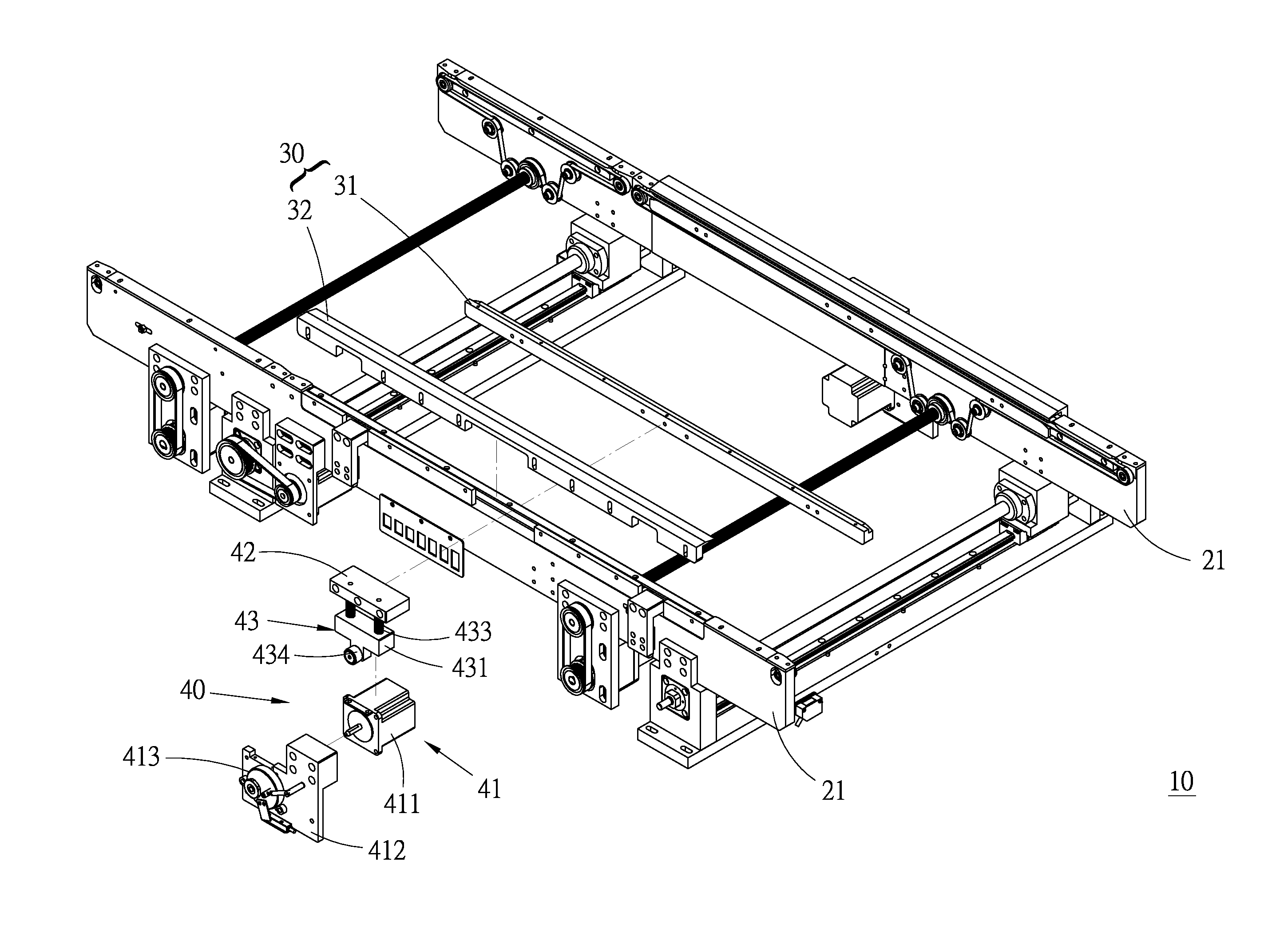
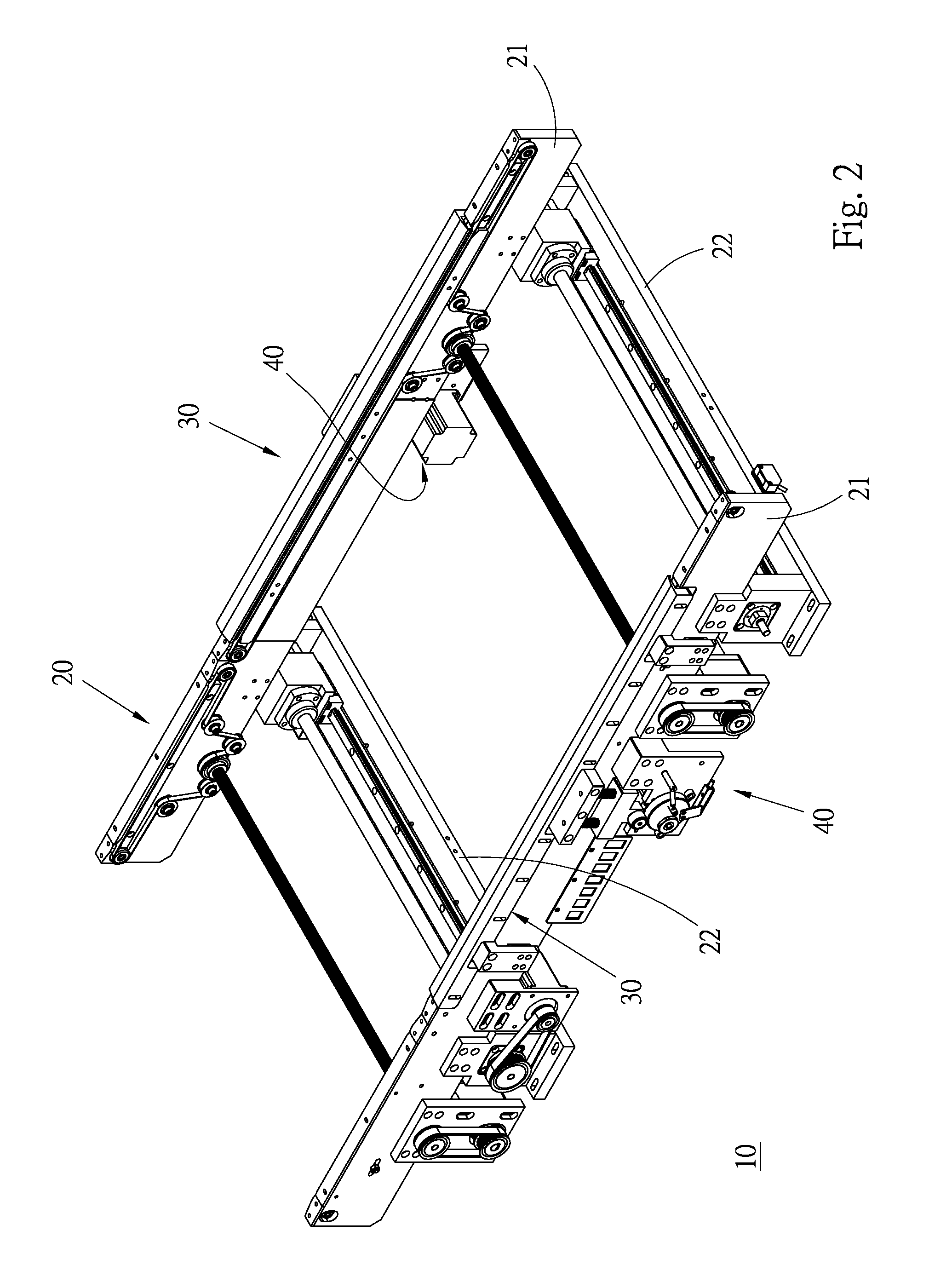
[0017]Please refer to FIGS. 2 to 6. According to a preferred embodiment of the present invention, the clamping mechanism 10 automatically adaptable to change of thickness of printed circuit board mainly includes a frame body 20, two clamping rail members 30 and two adjustment units 40.

[0018]The frame body 20 includes two horizontal elongated bar-like rail seats 21 in parallel to each other. The other components of the clamping mechanism 10 are arranged on the rail seats 21. Two locating bottom boards 22 are bridged between the rail seats 21 in parallel to each other for fixing the rail seats 21 in their true positions and reinforcing the frame body 20.

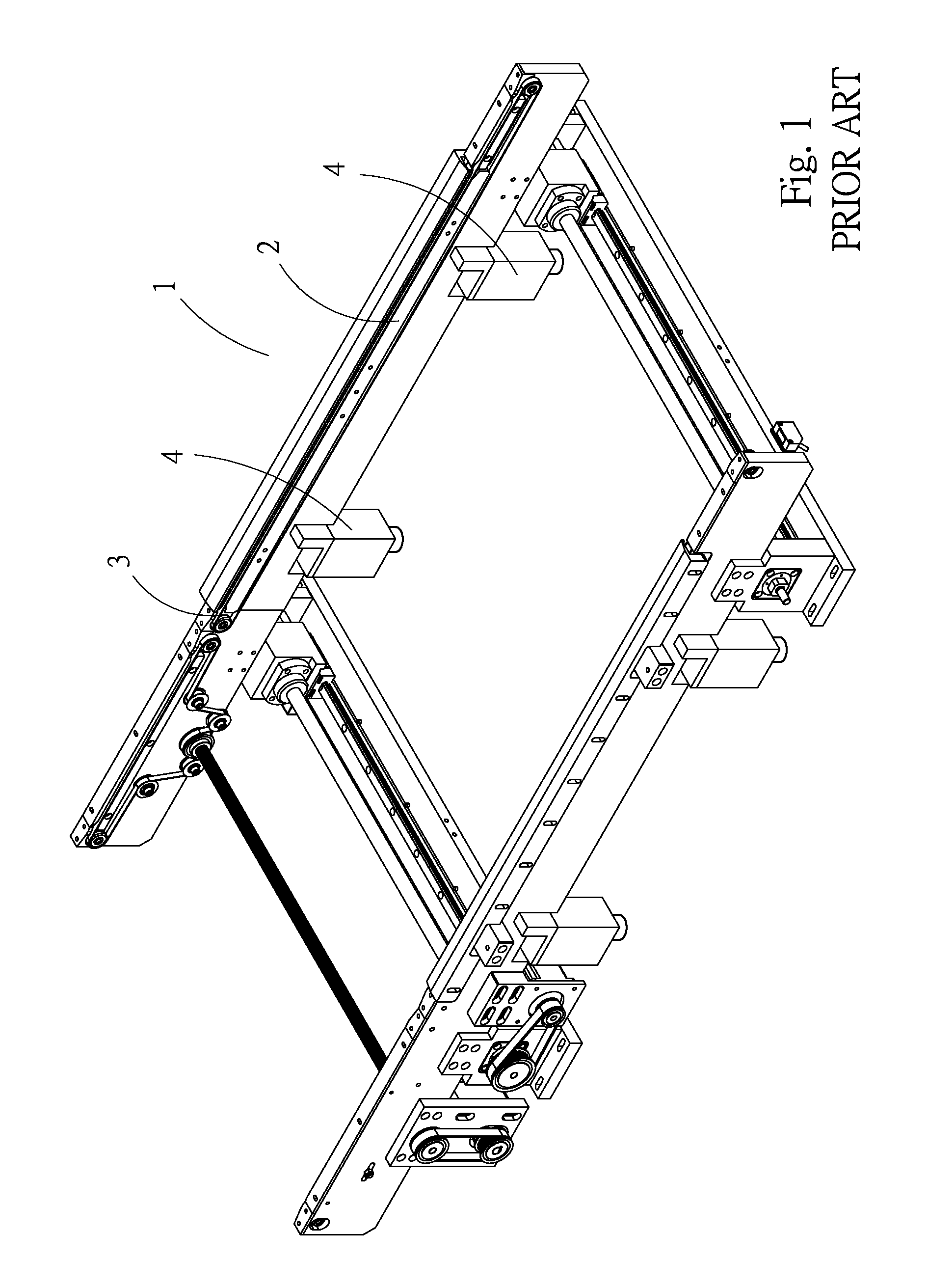
[0019]The clamping rail members 30 are respectively mounted on the rail seats 21 for clamping and holding two opposite sides of a printed circuit board and locating the same. By means of a conventional transmission mechanism, the held printed circuit board is moved along the length of the rail seats 21. This technique pertains to prior...


PUM


Abstract

A clamping mechanism automatically adaptable to change of thickness of printed circuit board includes: a frame body having two parallel rail seats; two clamping rail members respectively mounted on the rail seats for clamping a printed circuit board, each clamping rail member including a first clamping rail and a second clamping rail spaced from each other by a clamping gap; and two adjustment units for adjusting the clamping gap of the clamping rail members. Each the adjustment unit includes: a support section mounted on the frame body to provide a support face; a connection section, one end of the connection section being affixed to the first clamping rail, the other end of the connection section being positioned above the support face; and a floating section positioned between the connection section and the support section and supported on the support face to apply a resilient support force to the connection section.

Description

BACKGROUND OF THE INVENTION[0001]1. Field of the Invention[0002]The present invention relates generally to printed circuit board (PCB) manufacturing and processing technique, and more particularly to a clamping mechanism automatically adaptable to change of thickness of printed circuit board.[0003]2. Description of the Related Art[0004]A printed circuit board has a substrate made of such as glass epoxy material. Predetermined circuits are formed on the substrate by means of the conventional transfer printing and etching techniques. Then proper electronic components are electrically connected to the printed circuit board to serve as a part of an electronic equipment. All kinds of electronic equipments have become more and more complicated over the years. As a result, multilayer PCB substrate made of up to 100 layers by lamination has been developed instead of the traditional single-layer substrate. No matter how many layers the PCB substrate has, in the manufacturing process of the P...

Claims


Application Information

Patent Timeline
IPC IPC(8): B23Q3/06
CPCH05K13/0069
Inventor LIN, CHENG-FENGLIU, CHI-TAI
Owner HIWIN MIKROSYST
Why Eureka
Try Eureka