SVPWM (Space Vector Pulse Width Modulation) control method for Z-source inverter

A control method and technology of source inverter, which is applied in the equal direction of irreversible DC power input conversion to AC power output, can solve the problems of large inductor current and ripple, achieve small position change, stable inductor current ripple, The effect of reducing inductor current ripple

Inactive Publication Date: 2013-03-13
HARBIN INST OF TECH
View PDF2 Cites 18 Cited by
  • Summary
  • Abstract
  • Description
  • Claims
  • Application Information

AI Technical Summary

Problems solved by technology

[0008] The present invention is to solve the problem that in the existing SVPWM control method of the Z-source inverter, the straight-through zero vector is divided into six sections and inserted between adjacent zero vectors, non-zero vectors and two adjacent effective vectors, which will generate a The problem of the largest inductor current ripple, a SVPWM control method for Z-source inverter is provided

Method used


Image

  • SVPWM (Space Vector Pulse Width Modulation) control method for Z-source inverter
  • SVPWM (Space Vector Pulse Width Modulation) control method for Z-source inverter
  • SVPWM (Space Vector Pulse Width Modulation) control method for Z-source inverter

Examples


specific Embodiment approach 1

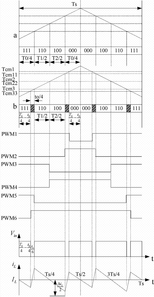
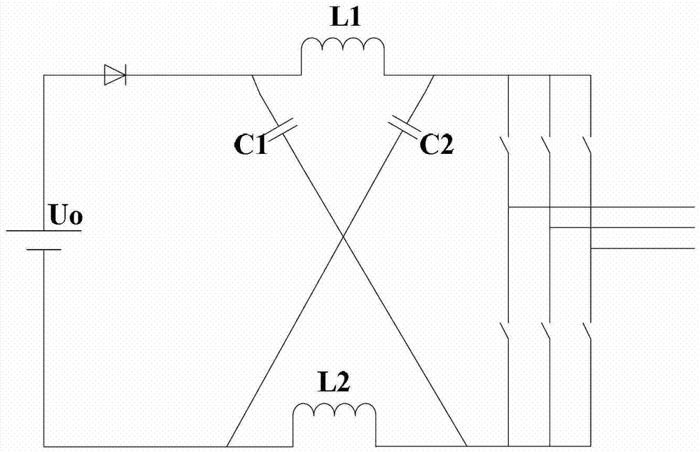
[0020] Specific implementation mode one: the following combination Figure 1 to Figure 3 Describe this embodiment, the SVPWM control method for the Z source inverter described in this embodiment, it is based on the traditional SVPWM control method, with 8 vectors to represent the state of the three switch tubes of the upper bridge arm of the inverter, the 8 vectors The vectors are 000, 001, 010, 100, 011, 101, 110, 111, 1 means on, 0 means off, among them, 000 and 111 are traditional zero vectors, the other six are valid vectors, the 8 vectors Divide the control interval into six sectors; the control method of each sector is the same;

[0021] Taking sector III as an example, in each PWM period Ts, the active vectors are arranged as 111, 110, 100, 000, 000, 100, 110, 111 from left to right, and the total action time of the traditional zero vector for T 0 , set the total action time through the zero vector as t 0 , 00 ≤T 0 , will pass through the total action time t of the ...

specific Embodiment approach 2

[0025] Specific implementation mode two: the following combination Figure 1 to Figure 3Describe this embodiment. This embodiment is a further description of Embodiment 1. In this embodiment, t 0 The value range of is: 00 ≤0.5Ts.

[0026] In this embodiment, t 0 The value range of is related to the boost ratio to be realized, generally 0 to 0.5 times the PWM switching period Ts.

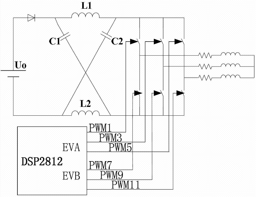
[0027] image 3 As shown, the control method of the present invention adopts TI C2000 series DSP TMS320F2812 to realize, and it is by DSP2812 event manager A, promptly PWM1, PWM3, PWM5 of EVA produces upper bridge arm three-way PWM control signal, by event manager B, That is, PWM7, PWM9, and PWM11 of EVB generate three PWM control signals of the lower bridge arm. After the six-way PWM signal is driven by the drive board circuit, the drive signal is sent to the IGBT of the inverter to control the operation of the Z source inverter.

[0028] The two groups of event managers can be controlled indep...


PUM


Abstract

The invention relates to an SVPWM (Space Vector Pulse Width Modulation) control method for a Z-source inverter, belongs to the technical field of inverter control and solves the problem of generation of a larger inductive current ripple caused by the existing SVPWM control method for the Z-source inverter. The states of three switching tubes of an upper bridge arm are represented by eight vectors, and the eight vectors divide a control interval into six sectors. For taking the third (III) sector as an example, the vectors taking actions in Ts in each SVPWM period are allocated sequentially from left to right as 111, 110, 100, 000, 000, 100, 110 and 111, wherein the total acting time of a traditional zero vector is set as T0; the total acting time of a direct-through zero vector is set as t0 which is greater than 0 and less than or equal to T0; and the total acting time t0 of the direct-through zero vector is divided into four sections inserted between the acting times of the traditional zero vector and an adjacent effective vector, thereby realizing SVPWM control of the Z-source inverter. The SVPWM control method is suitable for the SVPWM control of the Z-source inverter.

Description

technical field [0001] The invention relates to a SVPWM control method for a Z-source inverter, and belongs to the technical field of inverter control. Background technique [0002] There are 8 vectors in the traditional SVPWM control method, such as Figure 4 As shown, the eight vectors divide the entire interval into six sectors, and these eight vectors are respectively 000, 001, 010, 100, 011, 101, 110, and 111, representing the three switching tubes of the upper bridge arm of the inverter The state of the state, 1 represents conduction, 0 represents off, the state of the three switches of the lower bridge arm is opposite to that of the upper bridge arm. Among these 8 vectors, 000 and 111 are zero vectors, and the other six are valid vectors. According to the principle of vector synthesis, Figure 4 any vector in can be synthesized by two adjacent basic vectors among the eight basic vectors. In the practical application of the inverter, it is based on the vector The...

Claims


Application Information

Patent Timeline
Patent Type & Authority Applications(China)
IPC IPC(8): H02M7/48
Inventor 薛平张千帆董帅杨波李锦超那拓扑周超伟
Owner HARBIN INST OF TECH
Why Eureka
Try Eureka