Power reversal control method and power reversal control device for hybrid direct-current power transmission system

A DC transmission system and power flow reversal technology, applied in the direction of power transmission AC network, etc., can solve the problems of increasing the number of switching operations of filtering or reactive power compensation equipment, poor controllability of reactive power, and voltage fluctuations of interconnected power grids, reducing Switching times, stable DC power reversal, and the effect of realizing DC power reversal

Active Publication Date: 2015-05-20
NR ELECTRIC CO LTD +1
View PDF8 Cites 25 Cited by
  • Summary
  • Abstract
  • Description
  • Claims
  • Application Information

AI Technical Summary

Problems solved by technology

[0005] In the hybrid DC transmission system combining traditional DC transmission and flexible DC transmission, the active power of the traditional DC transmission system does not change linearly during the power flow reversal process, but there is a sudden change at the minimum power, although the sudden change is at the minimum power , but the minimum power when the voltage is high, when the interconnected power grid is weak, this minimum power will still bring a large impact
In addition, during the power flow reversal process, the removal of filtering or reactive power compensation equipment brought about by the converter blocking of the traditional DC transmission system and the re-investment of filtering or reactive power compensation equipment after power flow reversal not only increase the filtering or reactive power compensation. The number of switching operations of the equipment reduces their life, and the voltage of the interconnected grid has large fluctuations due to the poor controllability of reactive power, so a control method is needed to control the active and reactive power during the power flow reversal process. Unified and coordinated control of power to reduce the impact on the interconnected grid

Method used


Image

  • Power reversal control method and power reversal control device for hybrid direct-current power transmission system
  • Power reversal control method and power reversal control device for hybrid direct-current power transmission system
  • Power reversal control method and power reversal control device for hybrid direct-current power transmission system

Examples


Embodiment 1

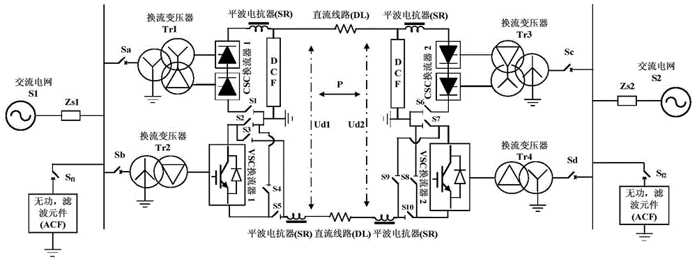
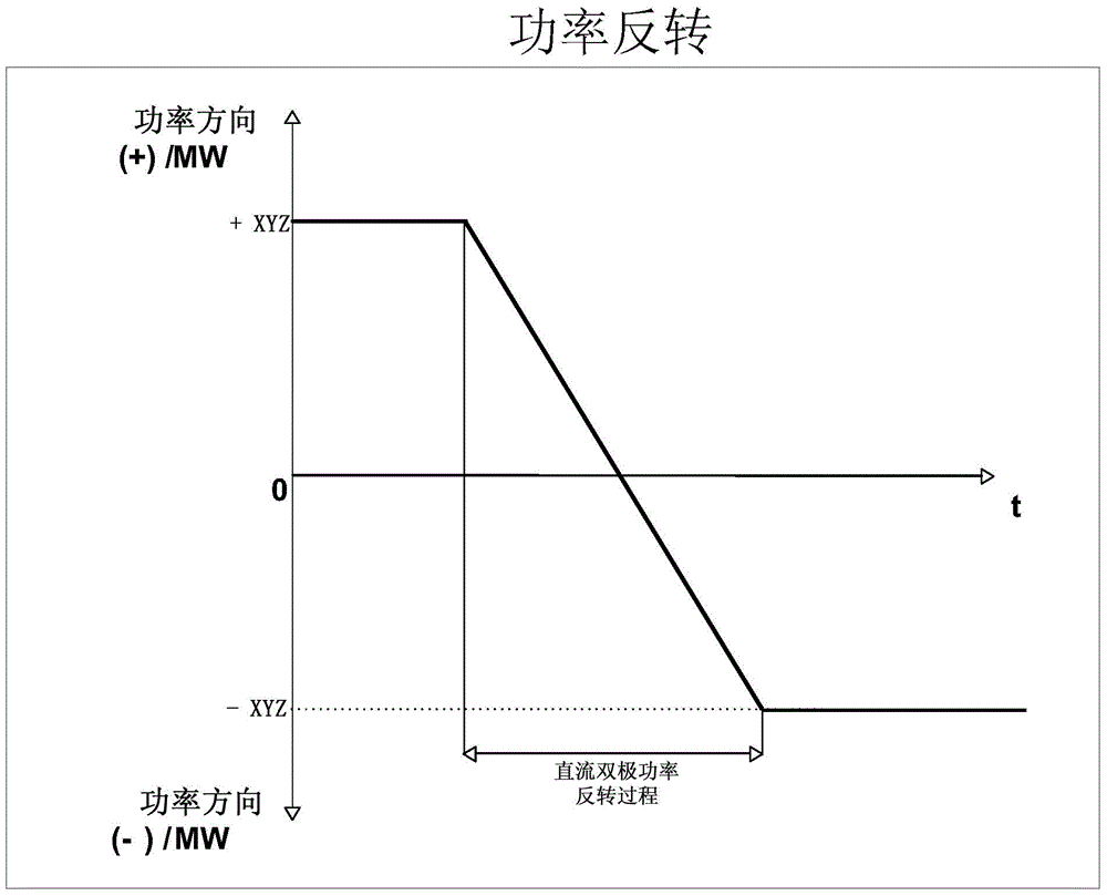
[0026] Example 1: The schematic diagram of bipolar active power changes in the process of power flow reversal is as follows figure 2 shown. The power flow reversal process of the hybrid bipolar DC transmission system specifically includes the following steps:

[0027] (1) Obtain the automatic power flow reversal start signal;

[0028] (2) Reduce the bipolar DC active power at a certain rate, and keep the bipolar DC active power linearly decreasing during the decline process, and at the same time, the net reactive power of the converter stations at both ends of the pole control based on VSC-HVDC technology is constant;

[0029] (3) After the DC current of the pole based on LCC-HVDC technology drops to the minimum current, the power will no longer drop. At this time, adjust the active power drop rate of the pole based on VSC-HVDC technology to keep the bipolar DC active power in a straight line;

[0030] (4) When the bipolar DC active power linearly decreases to an appropriat...

Embodiment 2

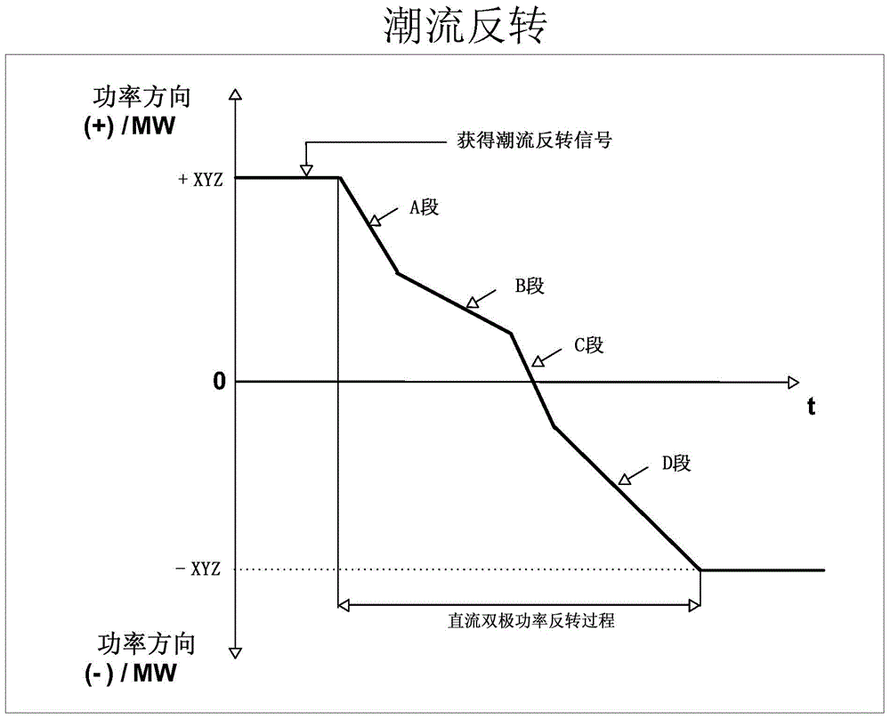
[0035] Example 2: The schematic diagram of bipolar active power changes during power flow reversal is as follows image 3 shown. The power flow reversal process of the hybrid bipolar DC transmission system specifically includes the following steps:

[0036] (1) Obtain the automatic power flow reversal start signal;

[0037] (2) Reduce the two-pole DC active power at a rate k1, such as image 3 As shown in the section A curve in , the bipolar DC active power keeps decreasing continuously during the decline process, and at the same time, the net reactive power of the converter stations at both ends of the pole control based on VSC-HVDC technology remains constant;

[0038] (3) After the DC current of the pole based on LCC-HVDC technology is reduced to the minimum current, the power will not drop, and the active power of the pole based on VSC-HVDC technology will continue to decline at the original rate, and the bipolar DC active power will continue to decline linearly; image...

Embodiment 3

[0047] Embodiment 3: The present invention also provides a device for controlling power flow reversal, such as Figure 4 As shown, the device includes a power flow reversal start judgment unit, an active power control unit, a reactive power control unit and a power flow reversal stop judgment unit, wherein

[0048] The power flow reversal start judging unit is used to collect the power flow reversal start signal, and the power flow reversal start signal is a signal or a composite signal of several signals;

[0049] The active power control unit is used to control the active power of the power flow reversal process;

[0050] The reactive power control unit is used to control the reactive power of the power flow reversal process;

[0051] The power flow reversal stop judging unit is used to collect a power flow reversal stop signal, and the power flow reversal stop signal is one signal or a composite signal of several signals.

[0052] When the power flow reversal start discri...


PUM


Abstract

The invention discloses a power reversal control method and a power reversal control device for a hybrid direct-current power transmission system. The hybrid direct-current power transmission system at least comprises double poles, wherein one pole is a conventional direct-current power transmission system (LCC-HVDC) based on a thyristor technology, the other pole is a flexible direct-current power transmission system (Flexible-HVDC) based on a full-control type power electronic device, and each pole is an independent direct-current power transmission sub system. In a power reversal process, active power conveyed by the hybrid direct-current power transmission system is continuously changed to be negative from positive, and net reactive power of a convertor system at each end of the hybrid direct-current power transmission system is kept constant in the power reversal process. The automatic power reversal method can effectively reduce interferences to an interconnected alternating-current network and realizes stable direct-current power reversal.

Description

technical field [0001] The invention relates to the field of hybrid direct current transmission, in particular to a power flow reversal control method and device for high voltage direct current transmission and hybrid extra high voltage direct current transmission systems. Background technique [0002] HVDC transmission systems can be divided into two types: traditional DC transmission systems (LCC-HVDC) based on thyristor technology; flexible HVDC systems based on fully controlled power electronic device technology (Flexible-HVDC). The traditional direct current transmission system (LCC-HVDC) has low cost, low loss, and mature operation technology. At present, almost all the operating direct current transmission systems in the world are LCC-HVDC systems, but the traditional direct current transmission system (LCC-HVDC) has inverter It is prone to commutation failure, strong dependence on the AC system, absorbs a large amount of reactive power, and the converter station occu...

Claims


Application Information

Patent Timeline
Patent Type & Authority Applications(China)
IPC IPC(8): H02J3/36
CPCY02E60/60H02J3/36
Inventor 赵文强王永平杨建明
Owner NR ELECTRIC CO LTD
Why Eureka
Try Eureka