Apparatus and method for producing video signals

a technology of video signal and apparatus, applied in the field of video signal production, can solve the problems of 720 line format, reduced vertical resolution, interlaced image suffers from the usual interlace artifacts, etc., and achieves the effect of reducing the number of pixels, reducing the perceived resolution, and reducing the perceived sharpness

Inactive Publication Date: 2010-11-16
FLORIDA ATLANTIC UNIVERSITY
View PDF25 Cites 10 Cited by
  • Summary
  • Abstract
  • Description
  • Claims
  • Application Information

AI Technical Summary

Benefits of technology

[0006]Diagonal sampling reduces the number of pixels in an image by a factor of two. This allows one to increase the frame rate from 301 to 60 P at the same bit rate. The perceived sharpness is actually slightly higher with this scan than with the cardinally sampled interlaced scan. Diagonal sampling matches the performance of the visual system and scene statistics better than cardinal sampling. All other things being equal, the perceived resolution is lowered by 1.4 rather than the two-fold reduction in number of pixels. In addition to this factor, the perceived resolution is further improved by almost a factor of two by going from interlace to progressive scan. The progressive scan does not have the interlace artifacts. The color signals can be derived from the RGB signals and transmitted with every other pixel on every other line. In this way, two color signals can be transmitted with half the bit rate of luminance. The color signals are also diagonally sampled. The display can be, for example, a matrix addressed light valve with the same filter pattern as the camera sensor. Alternatively, a standard color CRT, or a digitally addressed display, or any other suitable display, can be used.

Problems solved by technology

The interlaced image suffers from the usual interlace artifacts of interline flicker, line crawl and reduced vertical resolution.
The 720 line format has the disadvantage that a CRT in this format requires a higher horizontal scan frequency.

Method used


Image

  • Apparatus and method for producing video signals
  • Apparatus and method for producing video signals
  • Apparatus and method for producing video signals

Examples


Embodiment Construction

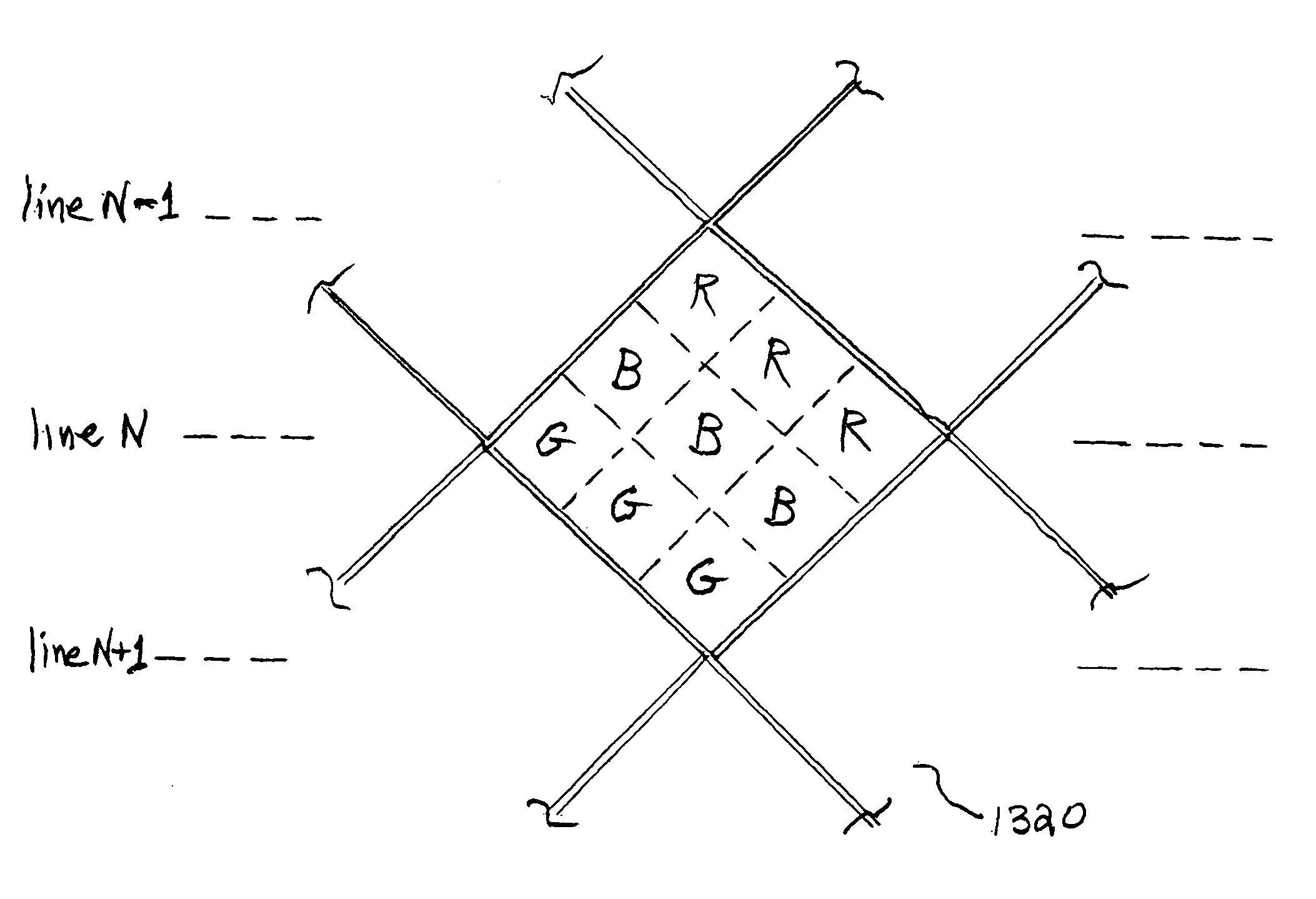
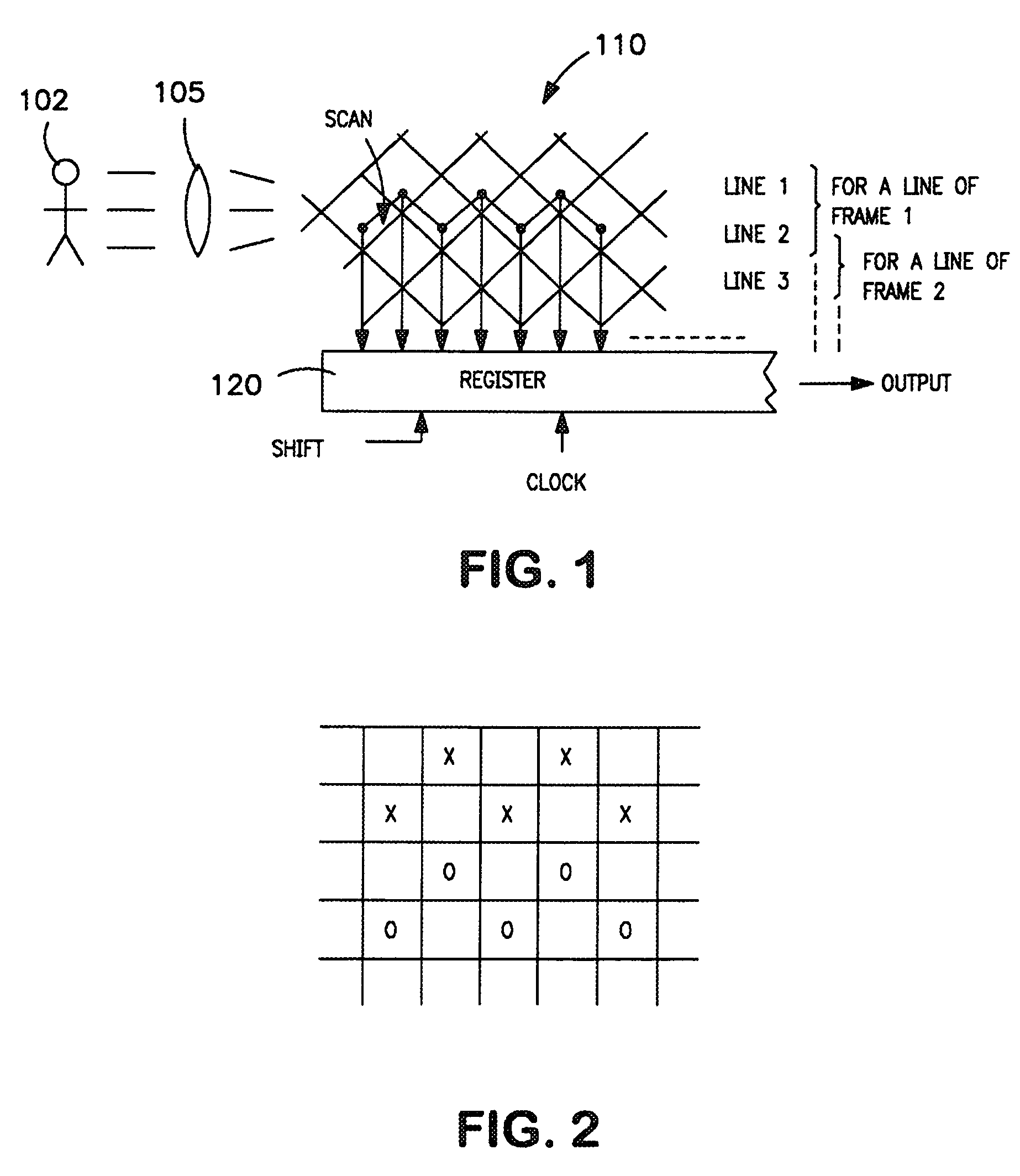
[0023]In FIG. 1, an image, which can be a moving image, from a scene 102, is projected by camera lens system 105 on a diagonally oriented solid state image sensor 110, a representative portion of which is shown in FIG. 1. For a diagonally sampled CCD, the pixels look as shown in the Figure. Lines 1, 2 and 3 are identified in the illustration, which shows how line pairs are clocked into the horizontal register 120 for lines of the first frame and lines of the second frame. The output has the two lines dot sequentially in its output. To make it compatible with interlace, two lines are clocked out at a time during one frame (lines 1 and 2, then 3 and 4, and so on). For the next frame, the register system shifts down one line and clocks out the next line pairs (lines 2 and 3, then 4 and 5, and so on).

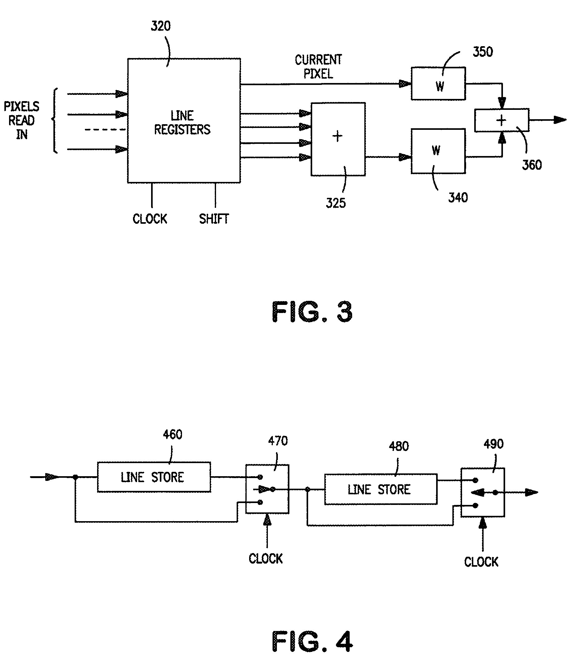
[0024]If the signal is to be obtained from a progressively scanned camera at 60 FPS, the signals can be derived from a cardinally sampled image as illustrated in FIGS. 2, 3, and 4. First, a...


PUM


Abstract

A method is disclosed for producing signals representative of an image of a scene including the following steps: providing an image sensor with a lenticular lens pattern thereon, and projecting the image onto the image sensor via the lenticular lens pattern, the image sensor having a pixel element pattern and the lenticular lens pattern having diamond shaped lenticles and being diagonally oriented with respect to the horizontal scanning direction of the pixel element pattern; and producing image-representative signals by reading out signals from the pixel elements of the image sensor.

Description

RELATED APPLICATIONS[0001]The present application is a continuation-in-part of U.S. patent application Ser. No. 10 / 360,571, filed Feb. 6, 2003 now U.S. Pat. No. 7,408,584, which claims priority from U.S. Provisional Patent Application Ser. No. 60 / 355,346, filed Feb. 6, 2002. The U.S. patent application Ser. No. 10 / 360,571 is, in turn, a continuation-in-part of U.S. patent application Ser. No. 10 / 227,597 (now U.S. Pat. No. 7,202,900), filed Aug. 22, 2002, which claims priority from U.S. Provisional Patent Application Ser. No. 60 / 314,209, filed Aug. 22, 2001.FIELD OF THE INVENTION[0002]This invention relates to the field of producing video signals, such as for television.BACKGROUND OF THE INVENTION[0003]As initial background, reference can be made, for example, to my U.S. Pat. Nos. 6,208,382, 6,266,093, 6,891,568, and 7,088,391, all assigned to the same assignee as the present application.[0004]The 720 60 P format for HDTV is almost totally incompatible with the 1080 301 format. Howev...

Claims


Application Information

Patent Timeline
Patent Type & Authority Patents(United States)
IPC IPC(8): H04N5/225H01L31/062H01L31/113
CPCH04N3/1562H04N5/3458H04N9/045H01L27/14645H04N25/40H04N25/447H04N25/134
Inventor GLENN, WILLIAM E.
Owner FLORIDA ATLANTIC UNIVERSITY
Why Eureka
Try Eureka