Deep dimple structure for head suspension component

Active Publication Date: 2010-11-16
HUTCHINSON TECH
View PDF11 Cites 44 Cited by
  • Summary
  • Abstract
  • Description
  • Claims
  • Application Information

AI Technical Summary

Benefits of technology

[0005]The present invention is a disk drive suspension or suspension component having an improved offset. The offset can be manufactured from thin stock and provide structural integrity by reducing stretching and thinning of the material at and around the offset. One embodiment of the offset structure in

Problems solved by technology

Such thinning is undesirable because it can, for

Method used


Image

  • Deep dimple structure for head suspension component
  • Deep dimple structure for head suspension component
  • Deep dimple structure for head suspension component

Examples


Example

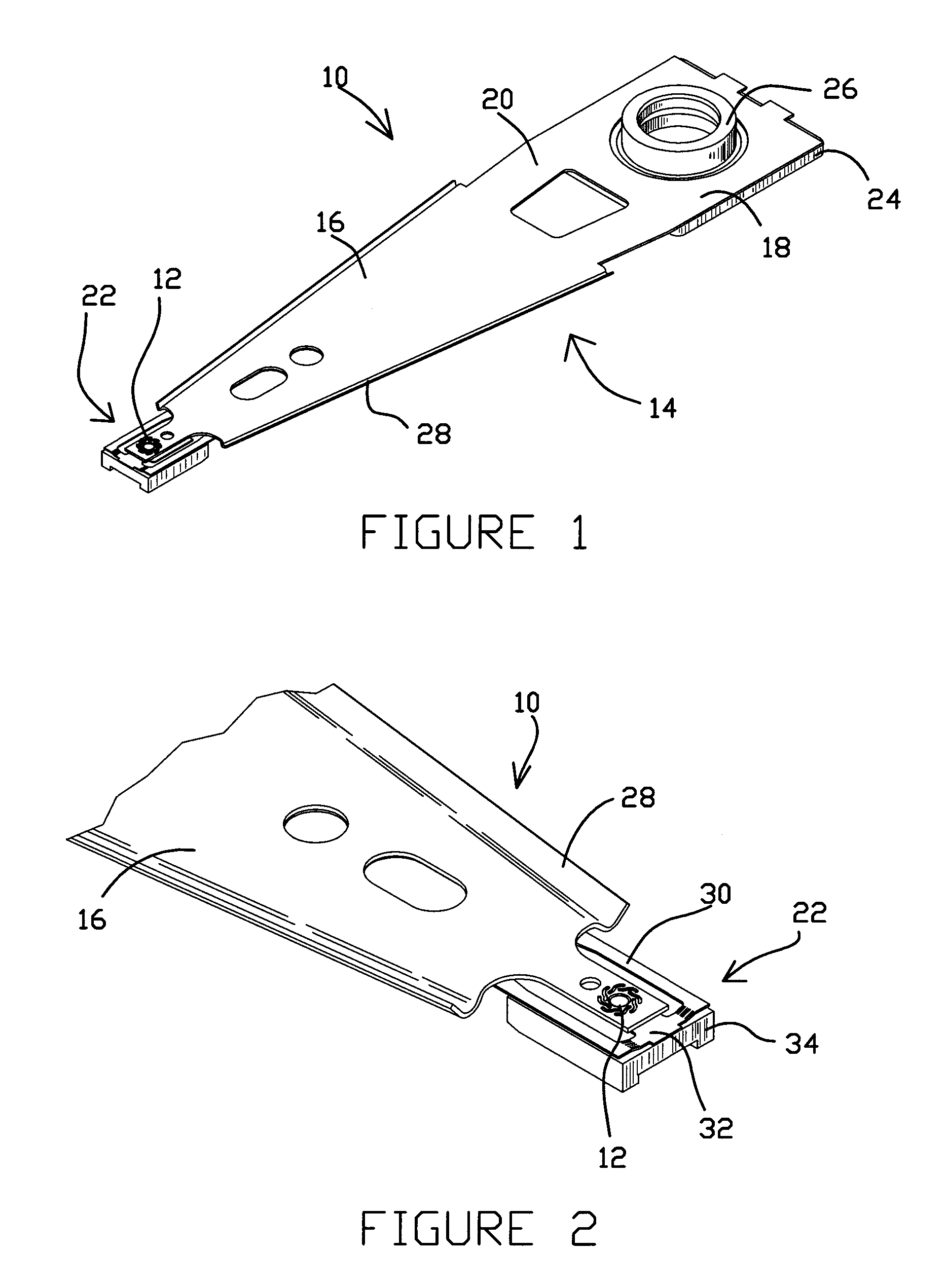
[0016]FIG. 1 shows head suspension 10 having offset structure 12 in accordance with one embodiment of the invention. Head suspension 10 includes load beam 14 having rigid region 16, mounting region 18, spring region 20 between rigid region 16 and mounting region 18, and flexure 22. A base plate 24 having boss tower 26 is mounted to the mounting region 18 of the suspension 10. As perhaps best shown in FIG. 2, load beam 14 also includes longitudinal stiffening rails 28 extending along the two side edges of rigid region 16. Flexure 22 includes arms 30 and a cantilevered slider mounting region 32 having a surface to which head slider 34 is mounted.

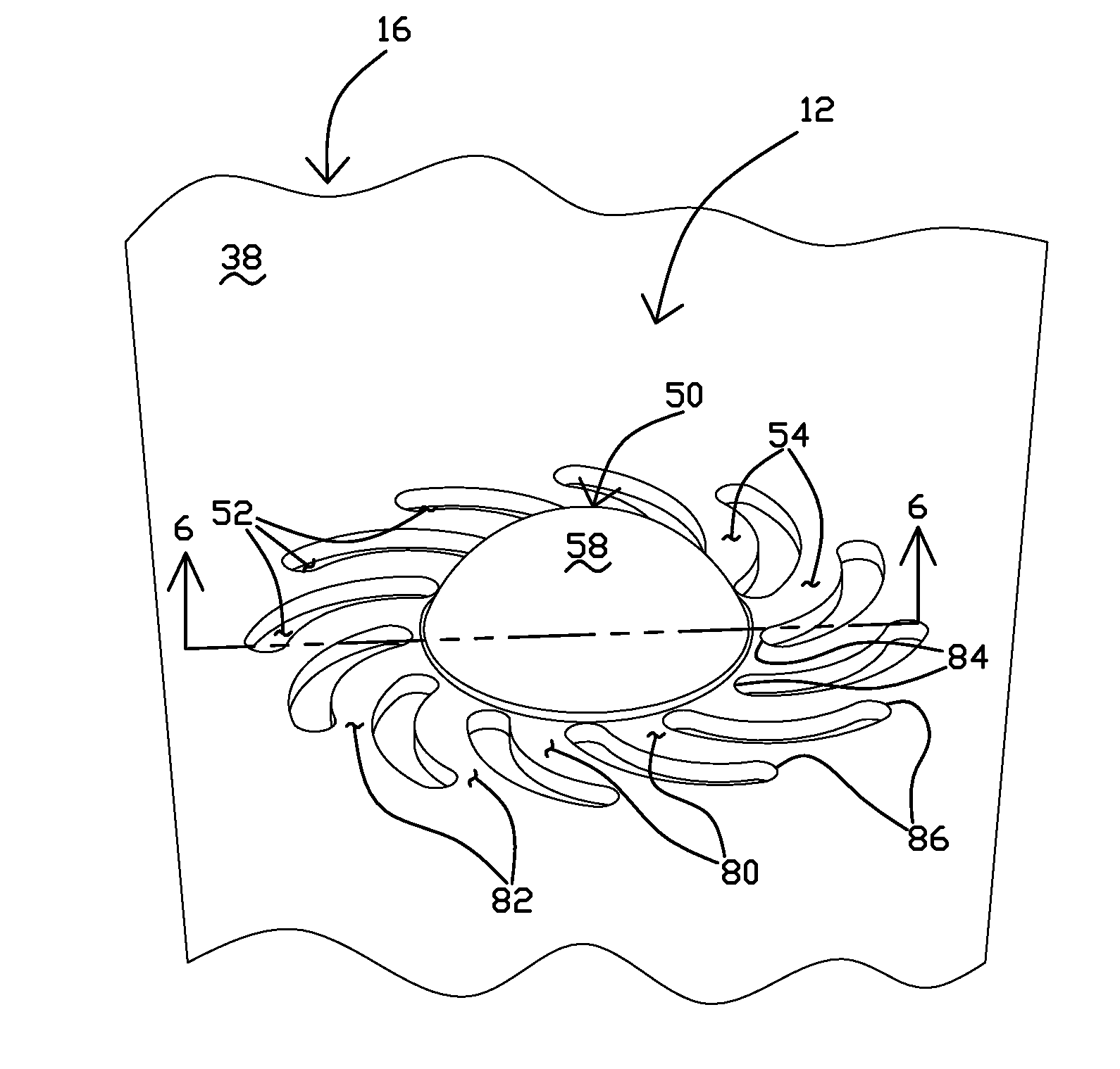
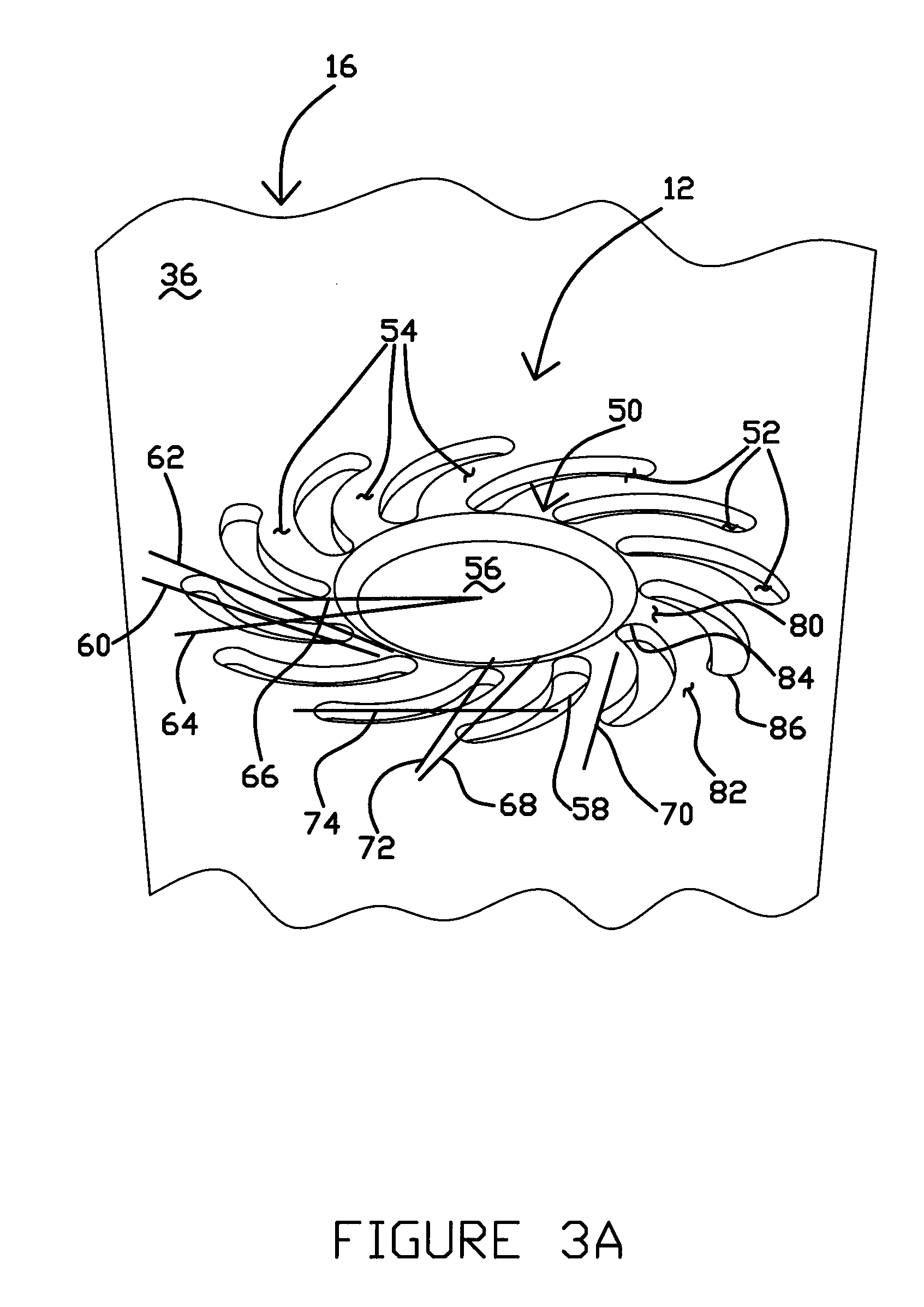
[0017]FIGS. 3A and 3B are detailed illustrations of a circular offset structure 12 on surfaces 36, 38 of rigid region 16 adjacent to slider mounting region 32 of flexure 22. As shown, offset structure 12 includes circular offset 50, a plurality of elongated voids 52 and a plurality of elongated links 54. Offset 50 extends out of the plane of t...


PUM


Abstract

Head suspension offset structures and methods of manufacture. The offset structure includes an offset extending out of a plane of a surface on which it is formed and a plurality of elongated voids and elongated links surrounding the offset. The links extend between the offset and the surface in both radial and circumferential direction. At least a portion of the elongated links and voids extend out of the plane of the surface, minimizing stretching and thinning of the material on and around the offset, and enhancing the integrity of the structure. The offset structure can be formed using conventional manufacturing processes.

Description

FIELD OF THE INVENTION[0001]The invention relates generally to a head suspension or head suspension component for use in a disk drive. In particular, the invention is a formed offset structure such as a dimple and a method for manufacturing the offset structure.BACKGROUND OF THE INVENTION[0002]Disk storage devices typically include a head suspension for positioning a head slider in close proximity to a rotating disk. Typical head suspensions include a load beam having a loading region at a distal end thereof, and a flexure interacting with the loading region at the distal end of the load beam. The flexure can be either integral with the load beam or it can be formed as a separate piece rigidly mounted on the load beam. The flexure typically includes a flexure tongue which is a cantilever region having one or more free ends on which the head slider is mounted. The head slider mounting region, i.e., the flexure tongue, is resiliently moveable with respect to the remainder of the flexu...

Claims


Application Information

Patent Timeline
IPC IPC(8): G11B5/48
CPCG11B5/4826
Inventor DOUGLAS, JOEL B.
Owner HUTCHINSON TECH
Why Eureka
Try Eureka