Airfoil trailing edge cooling

a trailing edge cooling and airfoil technology, applied in the direction of machines/engines, foundry patterns, machine/engines, etc., can solve the problems of reducing the cooling efficiency of airfoils, limiting casting designs, and achieving the lowest values of aerodynamic losses associated with such blades, so as to improve cooling characteristics and high thermal strain

Active Publication Date: 2008-10-21
RTX CORP
View PDF4 Cites 75 Cited by
  • Summary
  • Abstract
  • Description
  • Claims
  • Application Information

AI Technical Summary

Benefits of technology

[0011]Briefly, in accordance with one aspect of the invention, a trailing edge cooling design is provided for improving the internal profiles for Mach number, static pressure drop, and internal heat transfer coefficient distribution along the airfoil trailing edge.
[0012]In accordance with another aspect of the invention, a plurality of relatively small pedestals are formed, by the use of refractory metal cores, in an internal channel between the walls of the airfoil near the trailing edge so as to thereby provide improved cooling characteristics and avoid step wise profiles and their associated high thermal strains and mechanical fatigue problems in the airfoil trailing edge.

Problems solved by technology

The fine features may be difficult to manufacture and / or, once manufactured, may prove fragile.
The currently used ceramic cores limit casting designs because of their fragility and because cores with thickness dimensions of less than about 0.012-0.015 inches cannot currently be produced with acceptable casting yields.
First, the aerodynamic losses associated with such a blade attain the lowest values due to a thinner trailing edge.
This relatively high pressure loss leads to undesirable high aerodynamic losses.
In general, the external thermal load on the airfoil pressure side is about two times that of the suction side, and therefore, there is a greater potential for pressure side fatigue to occur on the airfoil pressure side.
Since the airfoil trailing edge responds faster than the rest of the airfoil due to its lower thermal mass; these areas are particularly prone to fatigue failure.
Crack nucleation leads to linkage with thermal-mechanical fatigue cracking, originating and propagating from the trailing edge.
As cracks propagate, load shakedown will occur throughout the blade as the load is redistributed to other portions of the trailing edge.
Load shakedown leads to overload conditions, or conditions where the stresses in the blade may be above yield stress of the material as the load bearing blade area has decreased due to cracking.
This is an irreversible effect leading in all likelihood to blade liberation and failure.
The step-wise profiles are undesirable as they lead to relatively high peaks in internal heat transfer coefficients at the walls of the blade.
These metal temperature differences lead to high thermal strains, which in conjunction with transient thermal stresses in the airfoil during take-off, in turn, lead to undesirable thermal-mechanical fatigue problems in the airfoil trailing edge.

Method used


Image

  • Airfoil trailing edge cooling
  • Airfoil trailing edge cooling
  • Airfoil trailing edge cooling

Examples


Embodiment Construction

[0021]The use of refractory metal core (RMC) casting techniques offer certain advantages over the prior art approach of casting with ceramic molds. Such a process is described in U.S. Patent Publication US2003 / 0075300 A1 assigned to the assignee of the present invention and incorporated herein by reference.

[0022]One of the advantages of this RMC casting technology as recognized by the applicants, is that individual elements can be made much smaller than with conventional casting technologies and the features can be customized to almost any shape. Accordingly, the applicants have employed this technology to produce a refined and improved trailing edge cooling channel.

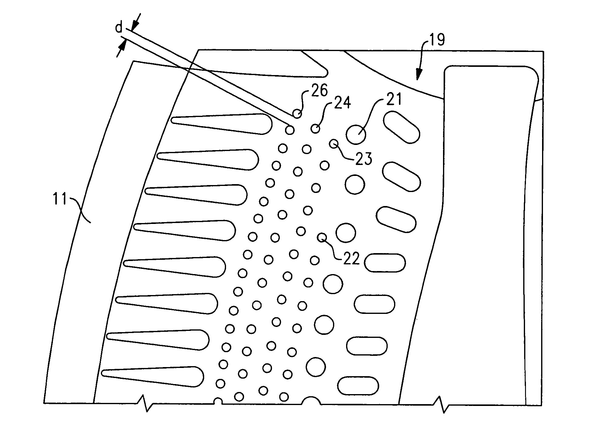
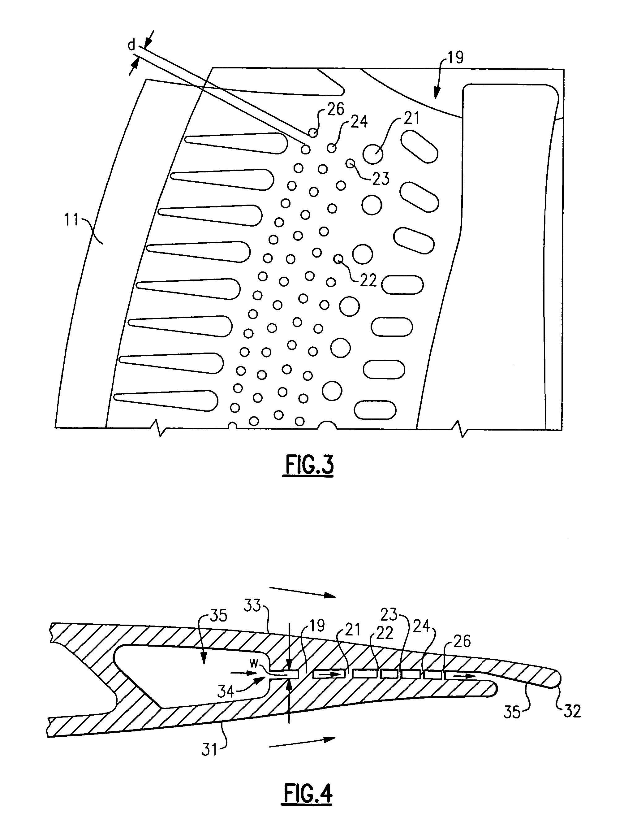
[0023]Referring to FIGS. 1 and 2, there is shown a turbine blade core constructed with the use of a refractory metal (i.e. a refractory metal core or RMC) 11. The RMC core 11 is shown in combination with a ceramic core 12 defining the radial supply cavity, with both of these elements representing negative features in the...


PUM

PropertyMeasurementUnit
widthaaaaaaaaaa
diametersaaaaaaaaaa
diameteraaaaaaaaaa

Abstract

A turbine airfoil includes a span wise extending cavity formed from a ceramic mold and a slot extending from the cooling air cavity to a trailing edge being formed by a refractory metal core. The refractory metal core facilitates the reduction in the size of the slot and also in the reduction in the size of pedestals which pass transversely through the slot to interconnect the pressure side to the suction side of the airfoil. The blade has a cutback feature to expose a back surface on the inner side of the suction side wall with dimples being formed on the back surface so as to enhance heat transfer characteristics thereof. Provision is made for fabricating the dimples by way of a photo etching process.

Description

BACKGROUND OF THE INVENTION[0001]This invention relates generally to cooling of airfoils and, more particularly, to a method and apparatus for cooling the trailing edges of gas turbine airfoils.[0002]A well developed field exists regarding the investment casting of internally-cooled turbine engine parts such as blades and vanes. In an exemplary process, a mold is prepared having one or more mold cavities, each having a shape generally corresponding to the part to be cast. An exemplary process for preparing the mold involves the use of one or more wax patterns of the part. The patterns are formed by molding wax over ceramic cores generally corresponding to positives of the cooling passages within the parts. In a shelling process, a ceramic shell is formed around one or more such patterns in well known fashion. The wax may be removed such as by melting in an autoclave. This leaves the mold comprising the shell having one or more part-defining compartments which, in turn, contain the c...

Claims


Application Information

Patent Timeline
Patent Type & Authority Patents(United States)
IPC IPC(8): F01D5/08
CPCB22C9/04B22C9/103F01D5/147F01D5/187F01D9/02F05D2260/22141F05D2240/12F05D2260/202F05D2260/221F05D2260/2212F05D2230/21F01D5/18
Inventor ALBERT, JASON E.CUNHA, FRANK J.
Owner RTX CORP
Why Eureka
Try Eureka