
Method of repairing concrete floors and system for same

Inactive Publication Date: 2010-11-23
BARNES AUDREY
View PDF50 Cites 52 Cited by
  • Summary
  • Abstract
  • Description
  • Claims
  • Application Information

AI Technical Summary

Benefits of technology

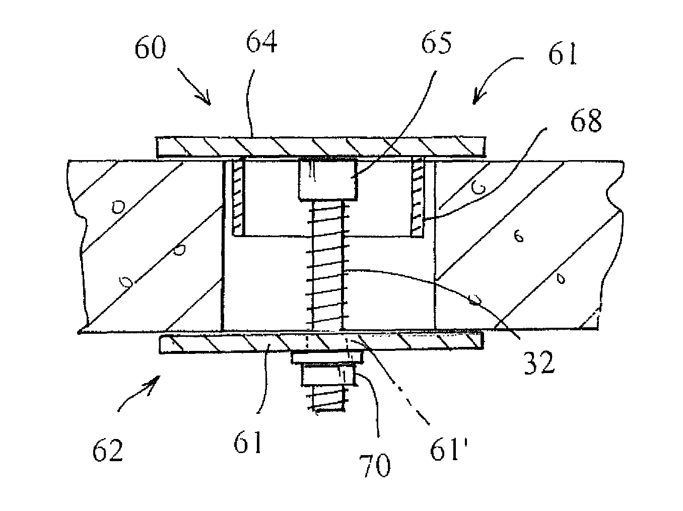
[0006]In a preferred form of the invention, a method of repairing a hole within a concrete floor comprises the steps of (a) providing a plug upper portion having a top plate of a size larger than the hole in the concrete floor and a neck of a size smaller than the hole in the concrete floor; (b) positioning the neck of the plug within the hole of the concrete floor and abutting the top plate against the top surface of the concrete floor surrounding the hole; (c) providing a plug lower portion having a bottom plate larger than the hole in the concrete floor; (d) providing coupling means for coupling the plug upper portion with the plug lower portion and for drawing the top plate and the bottom plate towards each other and into contact with

Problems solved by technology

Oftentimes, the reconfiguration of an office space requires that these wires or pipes be relocated, leaving a hole in the floor.

Method used


Image

  • Method of repairing concrete floors and system for same
  • Method of repairing concrete floors and system for same
  • Method of repairing concrete floors and system for same

Examples


Embodiment Construction

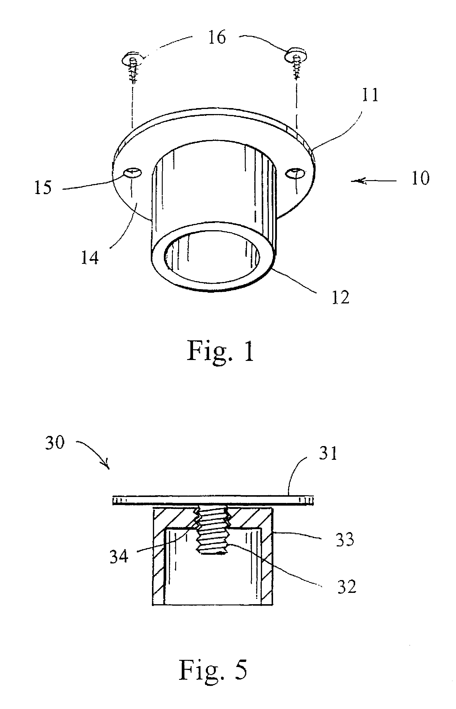
[0014]With reference next to the drawings, there is shown a floor plug 10 in a preferred form of the invention. The floor plug 10 includes a round, generally planar top plate 11 and a cylindrical neck 12 depending from the top plate 11. The diameter of the neck 12 is smaller than that of the top plate 11 so that the a portion of the top plate 11 forms a lip portion or lip 14 extending beyond the neck 12. The top plate 11 may include one or more mounting holes 15 through which mounting screws 16 may pass. Preferably, the floor plug is made of a galvanized metal, however, the plug may also be made of other suitable materials including, but not limited to, other metal, polymer, resin or plastic materials.

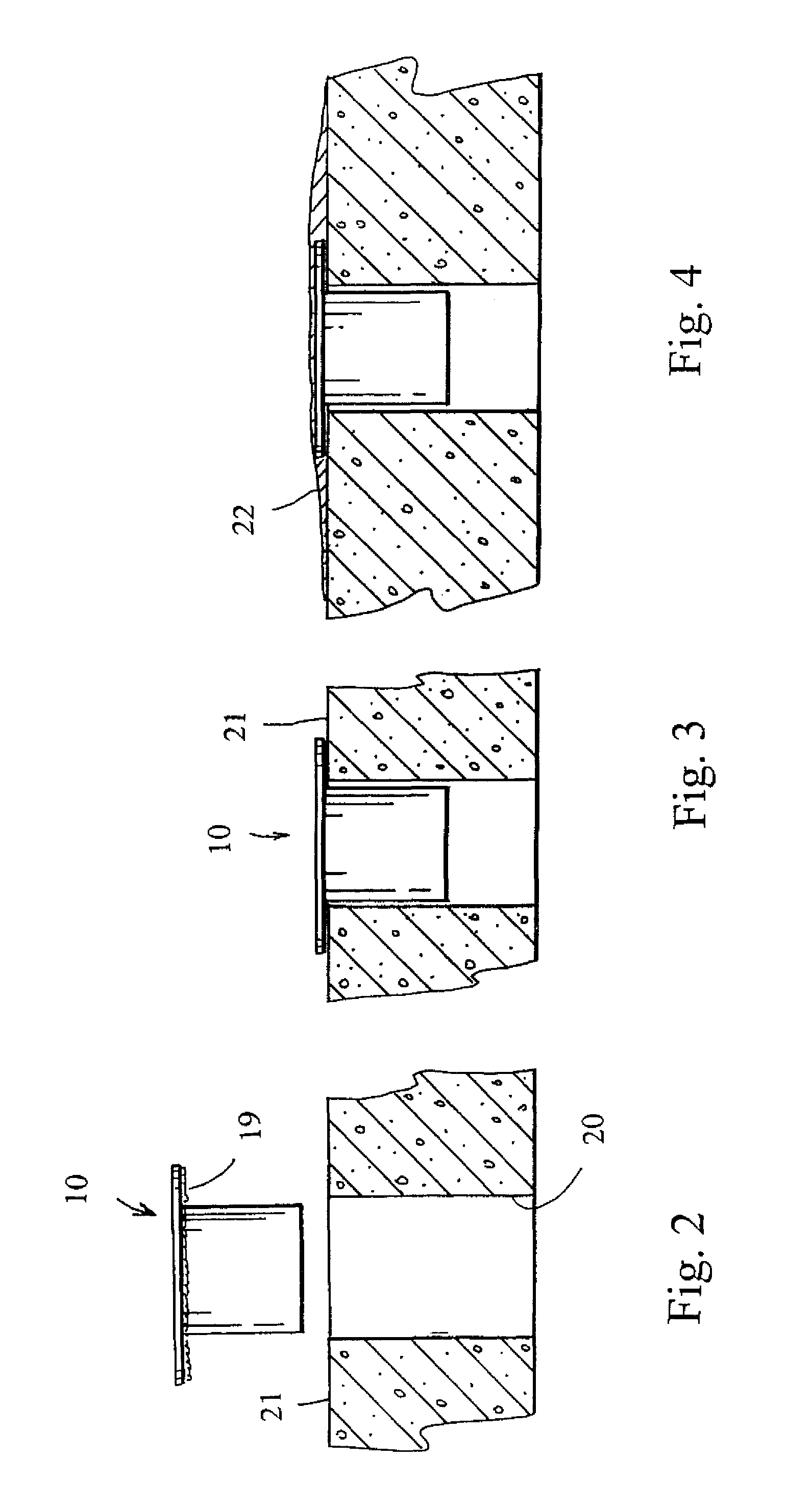
[0015]In use, an adhesive 19 is applied to the underside of the top plate lip 14 and the floor plug 10 is positioned so that its neck 12 fits within the bore hole 20 within a concrete floor 21. The adhesive 19 may also have a fire barrier property, such as Fire Barrier Sealant IC 15WB,...


PUM


Abstract

A floor plug (40) is disclosed having an upper portion (41) with a top plate (44) and a neck (48), a lower portion (42) with a bottom plate (51), and post (32) which coupled the two portions together and draws them towards each other sandwiching the floor therebetween. The upper portion is positioned within the bore hole (20) and the lower portion is coupled to the post so as to be threadably drawn against the underside of the floor. Once the adhesive has cured a viscous smoothing compound or concrete floor leveler is poured over the floor plug upper portion and surrounding concrete floor area. If necessary, the concrete floor leveler material is smoothed to provide a generally smooth or level surface.

Description

REFERENCE TO RELATED APPLICATION[0001]This is a continuation-in-part of U.S. patent application Ser. No. 11 / 649,554 filed Jan. 4, 2007.TECHNICAL FIELD[0002]This invention relates to a method of repairing a hole in a concrete floor and a system for repairing such.BACKGROUND OF THE INVENTION[0003]Concrete floors are oftentimes drilled or cored to form a bore hole through which electrical wiring or plumbing pipes are passed. Oftentimes, the reconfiguration of an office space requires that these wires or pipes be relocated, leaving a hole in the floor. As such, these holes must be repaired or filled so that an overlying carpet or tile may be placed over the hole.[0004]One method of repairing a bore hole has been to place a filling material into the hole and then applying a viscous smoothing compound over the hole. The smoothing compound then hardens to provide a finished surface.[0005]It is seen that a need exists for a method of repairing a hole within a concrete floor that provides a ...

Claims


Application Information

Patent Timeline
IPC IPC(8): E04B1/00
CPCE04G23/02E04G23/0203E04G23/0285E04G23/0288
Inventor BARNES, AUDREY
Owner BARNES AUDREY
Learn More