Kink protector for a line

a line protector and kink technology, applied in the direction of coupling device connection, nails, domestic objects, etc., can solve the problem of not being able to axially displace the line, and achieve the effect of facilitating the introduction of the mounting cap, and reducing the amount of clamping pressur

Inactive Publication Date: 2010-11-23
TRUPLAST KUNST STOFFTECHNIK GMBH
View PDF22 Cites 4 Cited by
  • Summary
  • Abstract
  • Description
  • Claims
  • Application Information

AI Technical Summary

Benefits of technology

[0008]The kink protector according to the invention is, after leading through of the line, simply pushed by its mounting cap into the correspondingly matched associated outlet stub of the connecting sleeve until detenting occurs, wherein the line is at the same time fixed within the mounting cap at least in axial direction. After the detenting process it is not possible to either axially displace the line in the kink protector or withdraw the kink protector by its mounting cap from the outlet stub without further measures. The kink protector thus fastened to the connecting sleeve ensures that the line cannot directly kink over at the connecting sleeve through an angle of 90°, but due to the effect of the support helix is led out of the connecting sleeve only in a curve. Cable breakages or cross-sectional constrictions of the hose are therefore prevented with certainty.
[0014]In addition to fixing of the line in the mounting cap by clamping action it can be provided that the mounting cap is, for prevention of rotation of the line in the mounting cap, provided with at least one pointed radial projection engaging the line and, for axial fixing of the line in the mounting cap, provided with an inwardly projecting annular rib. When the mounting cap is pushed into the outlet stub the at least one pointed radial projection and the annular rib engage in the circumferential surface of the line and in that case partially deform this inwardly so that a secure fixing of the line in the mounting cap is achieved.
[0015]In order to facilitate introduction of the mounting cap into the outlet stub it is of advantage if the clamping section of the mounting cap is conically formed at its free end. As a result, not only the introduction of the mounting cap, which has a slight oversize by comparison with the internal dimensions of the outlet stub, into the outline stub is facilitated, but at the same time the clamping pressure exerted by the mounting cap on the line which has been led through is increased.

Problems solved by technology

After the detenting process it is not possible to either axially displace the line in the kink protector or withdraw the kink protector by its mounting cap from the outlet stub without further measures.

Method used


Image

  • Kink protector for a line
  • Kink protector for a line
  • Kink protector for a line

Examples


Embodiment Construction

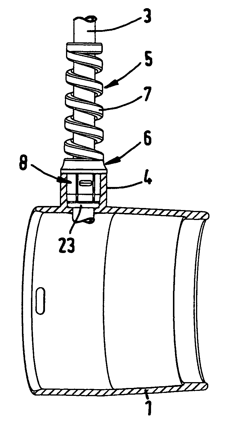
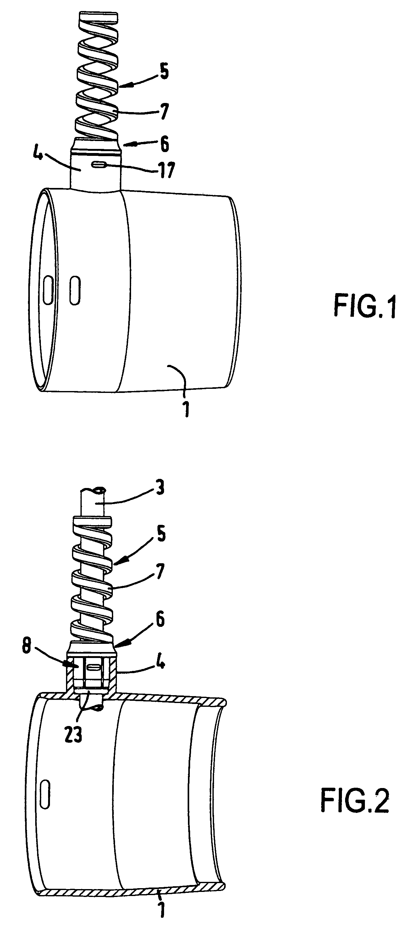
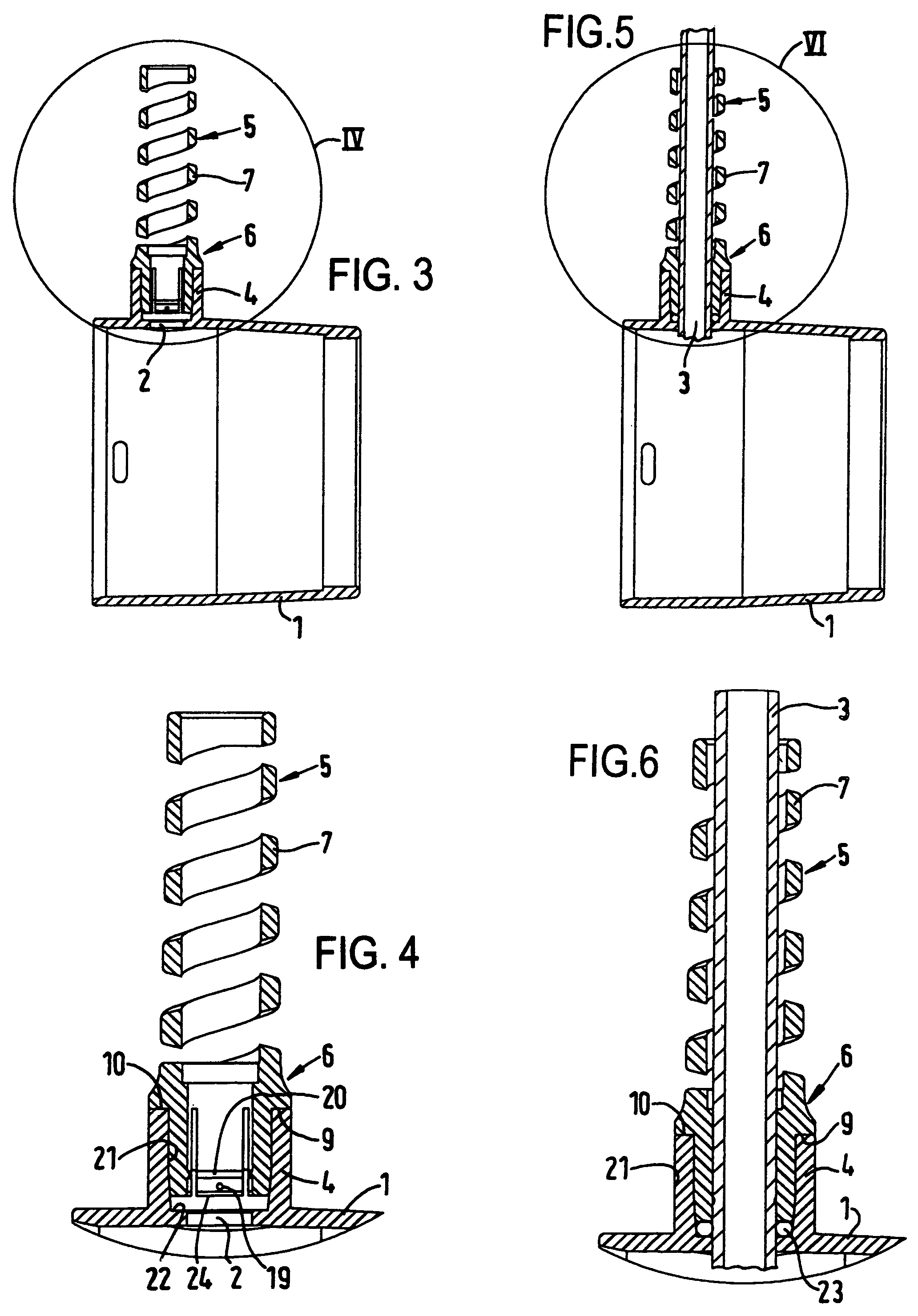
[0030]A connecting sleeve 1, which is typical for vacuum cleaner hoses and in which is disposed at a wall opening 2 through which a line 3 located in the hose interior is led or to be led outwardly, is apparent from FIGS. 1 to 6. An integrally formed outlet stub 4 for the line 3 is connected with the wall opening 2 of the connecting sleeve 1, which is injection-molded from a thermoplastic plastics material.

[0031]The kink protector 5, which is to be fastened to the connecting sleeve 1, for the line 3 has a mounting cap 6 and a resilient support helix 7 integrally injection-molded therewith from a thermoplastic plastics material. The line 3 is to be led through the mounting cap 6 and the support helix 7 as evident from, for example, FIGS. 5 and 6, wherein a radial spacing as movement play is provided between the inner circumferential surface of the support helix and the outer circumferential surface of the line 3, whereas the mounting cap 6 tightly surrounds, by its substantially cyli...


PUM


Abstract

A kink protector for a line which is led outwardly through a wall opening in a connecting sleeve of a hose or a pipe. The kink protector has a mounting cap which encloses the line, and a support helix which is integral with the cap and surrounds the line and which is resilient in bending. An outlet stub is provided at the connecting sleeve and is connected with the wall opening and into which the mounting cap can be pushed with at least axial fixing of the line in mechanically positive and detenting manner for the line.

Description

TECHNICAL FIELD[0001]The invention relates to a kink protector for a line, which is led outwardly through a wall opening in a connecting sleeve of a hose or a pipe, particularly a vacuum cleaner hose.[0002]The item here termed line is a cable enclosing electrical conductors or a hose conducting liquid or air.STATE OF THE ART[0003]In a known vacuum cleaner hose with a connecting sleeve, for example as disclosed in U.S. Pat. No. 6,722,904, electrical conductors are led outwardly through a wall opening. A kink protector for the electrical line is not, in that case, illustrated.[0004]In a right-angled departure of a line from a connecting sleeve at a hose / pipe a line bent over outwardly at the outside will, without anti-kink protection, kink. In that event cables can break in the case of electrical conductors or hoses conducting liquid or air can be so narrowed in their cross-section that throughflow is reduced and in the extreme case completely interrupted.[0005]Anti-kink or anti-bendi...

Claims


Application Information

Patent Timeline
Patent Type & Authority Patents(United States)
IPC IPC(8): F16B15/00
CPCA47L9/246F16L3/015H01R13/562
Inventor LINHART, GEORG PETERLINHART, CHRISTIAN NORBERT
Owner TRUPLAST KUNST STOFFTECHNIK GMBH
Why Eureka
Try Eureka