Telecommunications connector

a technology of telecommunications connectors and connectors, applied in the direction of coupling contact members, coupling device connections, contact members penetrating/cutting insulation/cable strands, etc., can solve the problems of mode conversion noise or crosstalk between, compensating elements

Active Publication Date: 2010-11-23
BELDEN CDT CANADA
View PDF171 Cites 75 Cited by
  • Summary
  • Abstract
  • Description
  • Claims
  • Application Information

AI Technical Summary

Problems solved by technology

On the other hand, the capacitive couplings between the pairs 1-2 and 3-6 and the pairs 3-6 and 7-8 are not equal for all conductors, which gives rise to, among others, mode conversion noise or crosstalk between the pairs (e.g. differential mode to common mode NEXT and vice-versa), a significant problem when attempting to comply with increasingly demanding industry standards.
However, one drawback of these prior art networks is that the compensating elements, be they inductive or capacitive, are located away from the point of contact between the terminal contacts of the plug and the contact elements of the connector.

Method used


Image

  • Telecommunications connector
  • Telecommunications connector
  • Telecommunications connector

Examples


Embodiment Construction

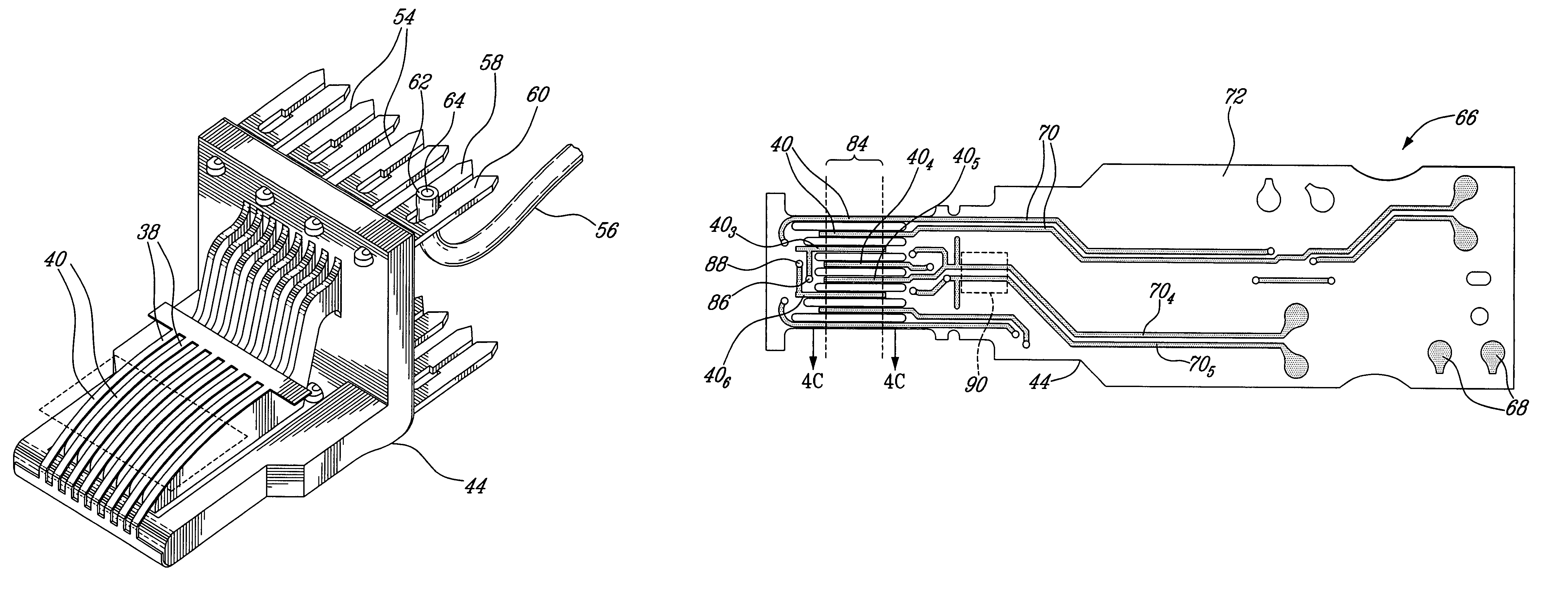
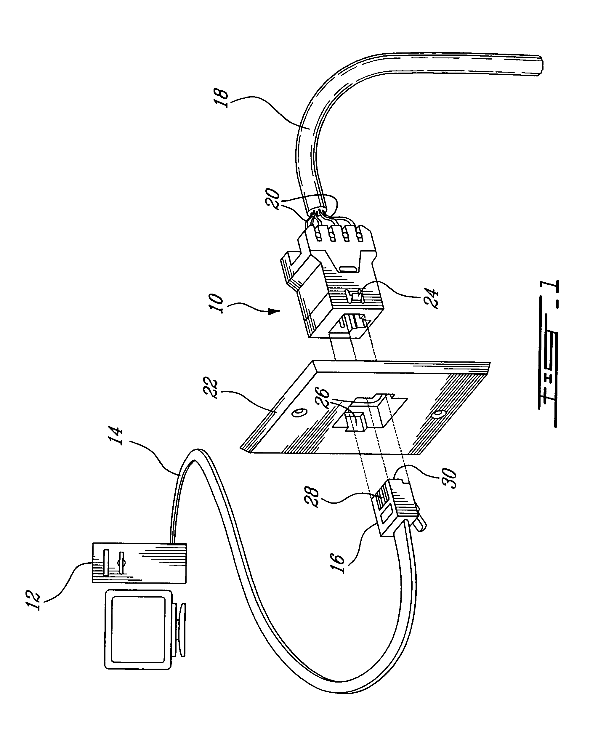
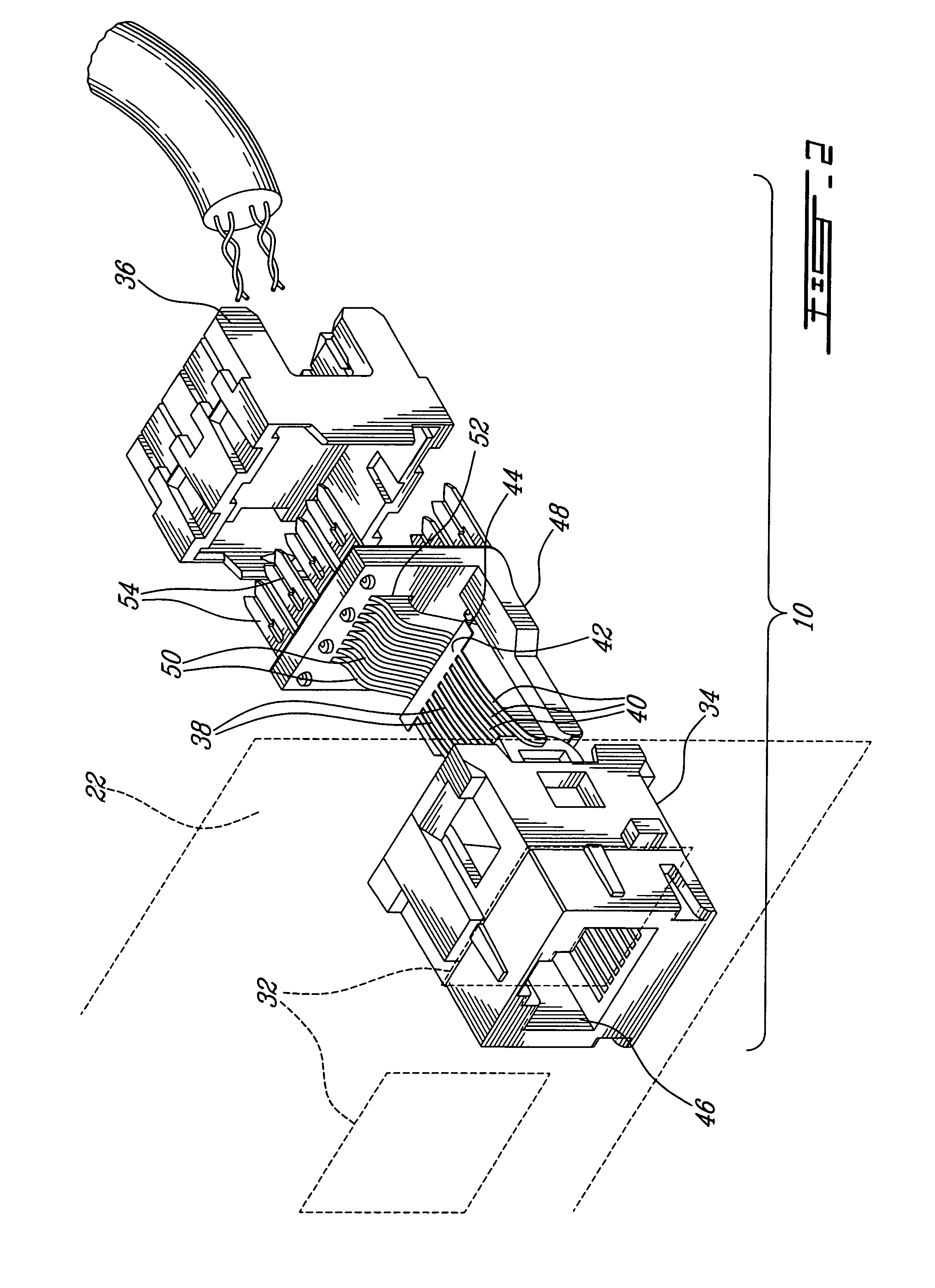
[0024]Referring now to FIG. 1, an illustrative embodiment of a connector, generally referred to using the reference numeral 10, will now be described. As known in the art user equipment as in 12 typically gains access to a local area network (LAN) or the like (not shown) via a network cable 14 comprised of a plurality of twisted pairs of conductors (not shown). The network cable 14 is terminated by a plug 16 which is adapted for insertion into (and removal from) the connector 10. The connector 10 terminates a communications cable 18 which, at an opposite end, is terminated by other networking equipment such as switches, hubs, routers, repeaters and the like (all not shown). Both the network cable 14 and the communications cable 18 are comprised of typically the same number of twisted pairs of conductors as in 20.

[0025]Still referring to FIG. 1, the connector 10, which is typically mounted flush with a wall or the like (not shown) behind which the communications cable 18 is hidden, i...


PUM


Abstract

A contact element and mechanism for use in a connector, the connector comprising a socket adapted for receiving a cable plug comprising a terminal contact. The contact element and mechanism comprise a flexible dielectric substrate and a first conductive strip on a first surface of the substrate. When the plug is inserted into the socket, the terminal contact comes into contact with the conductive strip.There is also provided a compensating connector for interconnection with a cable plug, the plug comprising a plurality of terminal contacts. The connector comprises a socket adapted for receiving the plug, a plurality of contact elements disposed in the socket, each of the contact elements comprising a conductive strip, and a compensation network comprised of a plurality of compensating elements. Each of the compensating elements is located adjacent to one of the contact elements. When the plug is inserted into the socket, each of the terminal contacts comes into contact with a predetermined one of the conductive strips.

Description

[0001]The present invention claims the benefit of a commonly assigned provisional application entitled “Connector”, which was filed on Apr. 19, 2004 and assigned Ser. No. 60 / 562,992. The entire contents of the foregoing provisional patent application are hereby incorporated by reference.FIELD OF THE INVENTION[0002]The present invention relates to a telecommunications connector. In particular, the present invention relates to a telecommunications connector comprised of a plurality of contact points having a compensating element at the point of contact.BACKGROUND TO THE INVENTION[0003]Connectors, or connector jacks, are adapted to receive plugs for the interconnection of telecommunication cables and equipment, a good example thereof being connectors and plugs which conform to the ubiquitous RJ-45 standard. As known in the art, as the plug is inserted into the connector a series of terminal contacts exposed along an edge of the plug come into contact with a corresponding series of cont...

Claims


Application Information

Patent Timeline
Patent Type & Authority Patents(United States)
IPC IPC(8): H01R24/00H01R4/24H01R9/03H01R12/08H01R13/00H01R13/03H01R13/33H01R13/6466H01R13/66H01R13/719H01R13/74H01R24/58H01R24/64H01R24/76H05K1/11
CPCH01R13/6466H01R13/6658H01R24/64H01R13/035H05K1/147H05K2201/10189H01R13/6464
Inventor MILLETTE, LUCBOHBOT, MICHELSIGOUIN, GILLESSIEV, VIRAK
Owner BELDEN CDT CANADA
Why Eureka
Try Eureka