Antenna apparatus utilizing minute loop antenna and radio communication apparatus using the same antenna apparatus

a technology of radio communication apparatus and minute loop antenna, applied in the field of antenna apparatus, can solve problems such as the decrease of antenna gain

Active Publication Date: 2006-06-01
PANASONIC CORP
View PDF12 Cites 124 Cited by
  • Summary
  • Abstract
  • Description
  • Claims
  • Application Information

AI Technical Summary

Benefits of technology

[0006] It is an object of the present invention to provide an antenna apparatus and a radio communication apparatus using the same antenna apparatus, each capable of solving the above-mentioned problems, and attaining a antenna gain higher than a conventional minute loop antenna whether a conductor is located closely or apart therefrom.

Problems solved by technology

The conventional minute loop antenna exhibits a favorable antenna gain characteristic when a conductor such as a metal plate, a human body or the like is located closely to the radio apparatus or the antenna, however, there is caused such a problem that the antenna gain decreases when the conductor is located apart therefrom.

Method used


Image

  • Antenna apparatus utilizing minute loop antenna and radio communication apparatus using the same antenna apparatus
  • Antenna apparatus utilizing minute loop antenna and radio communication apparatus using the same antenna apparatus
  • Antenna apparatus utilizing minute loop antenna and radio communication apparatus using the same antenna apparatus

Examples


first preferred embodiment

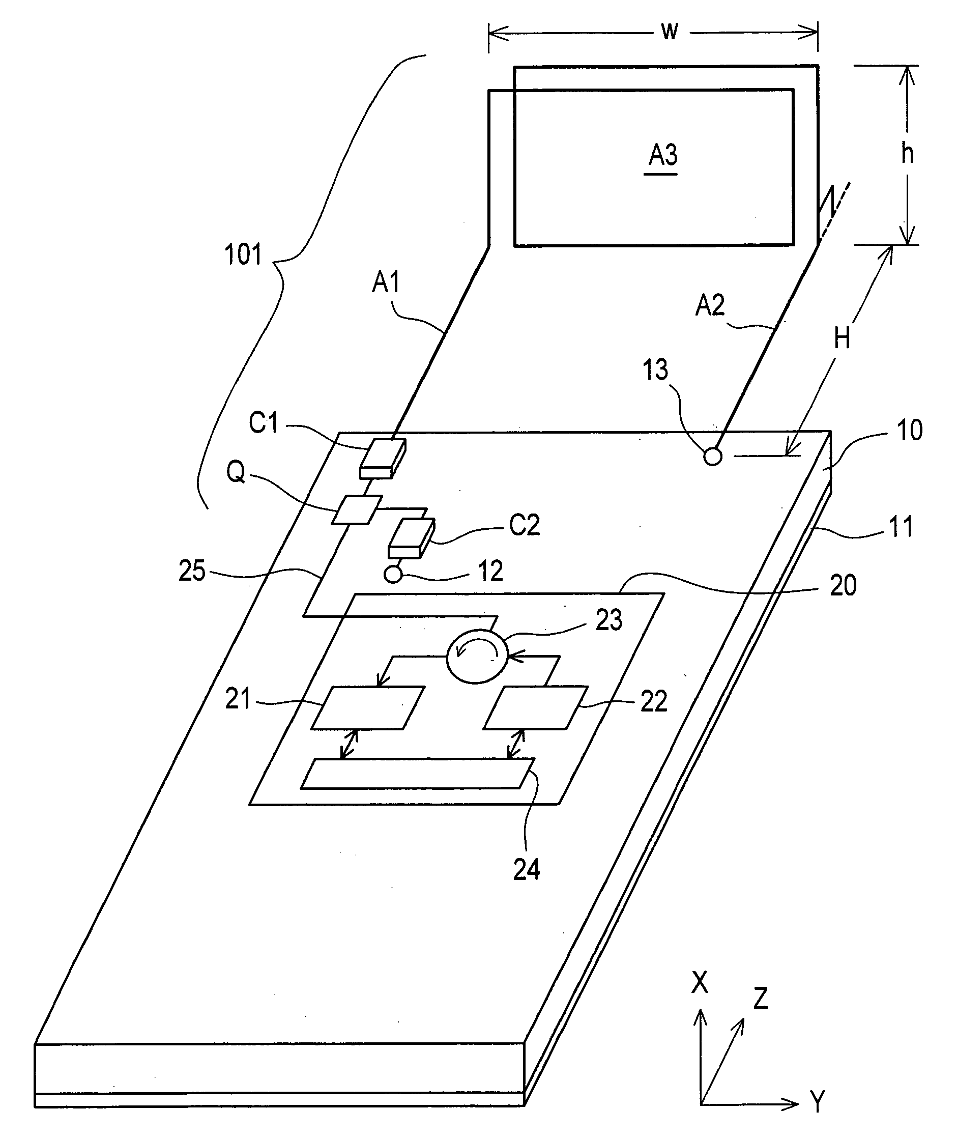
[0090]FIG. 1 is a perspective view showing a configuration of an antenna apparatus 101 according to a first preferred embodiment of the present invention. In FIG. 1, the antenna apparatus 101 according to the first preferred embodiment is characterized by including the following:

[0091] (a) two antenna elements A1 and A2 which are substantially linear and arranged substantially in parallel to each other;

[0092] (b) a rectangular minute loop antenna A3, which is connected to be inserted between these antenna elements A1 and A2, where the rectangular minute loop antenna A3 is provided in a direction perpendicular to the antenna elements A1 and A2, and has a number N of turns (N=1.5); and

[0093] (c) a capacitor C1 which is connected to be inserted between the antenna element A1 and a feeding point Q.

[0094] Referring to FIG. 1, the feeding point Q is provided on an upper left edge portion of a dielectric substrate 10 which has a grounding conductor 11 formed on the whole rear surface i...

second preferred embodiment

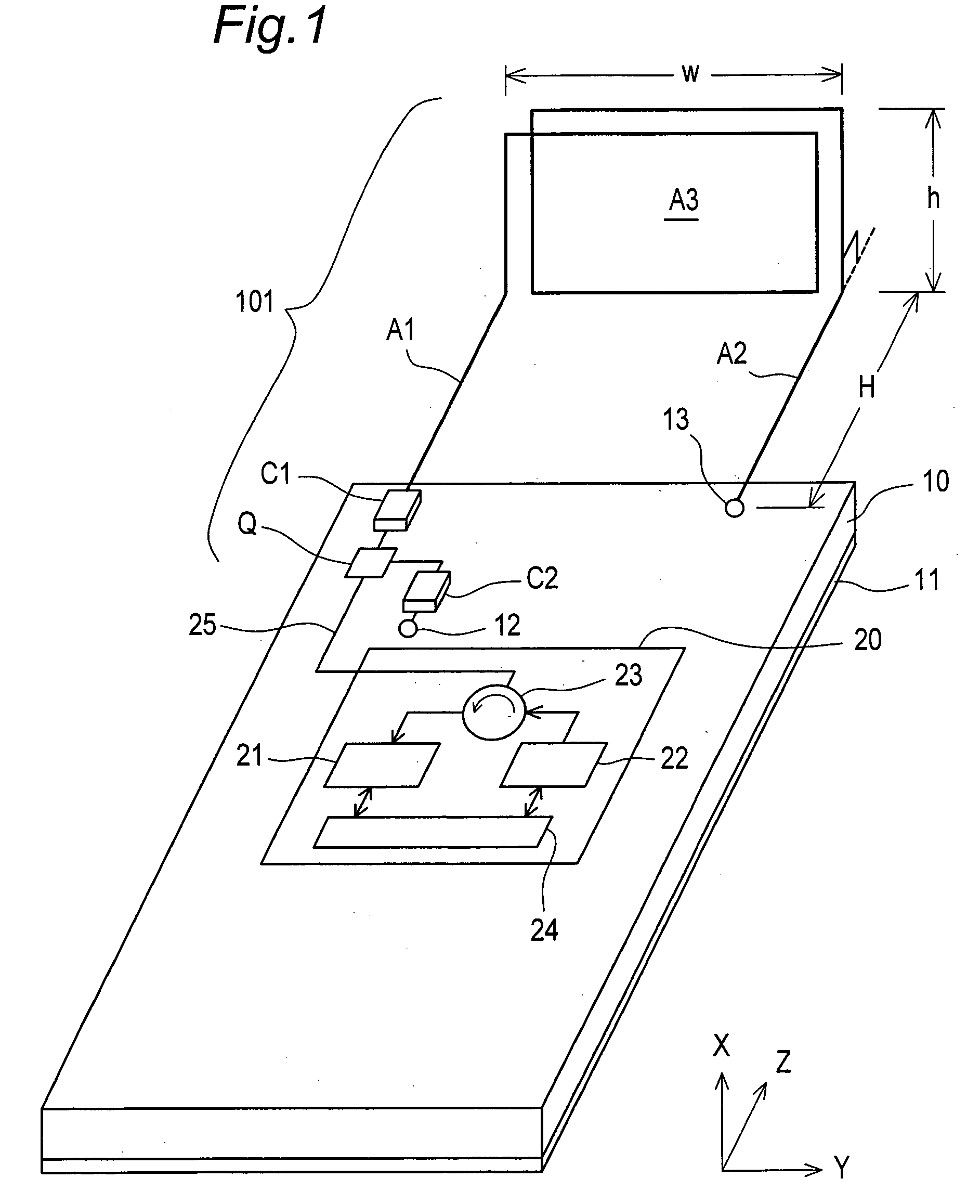
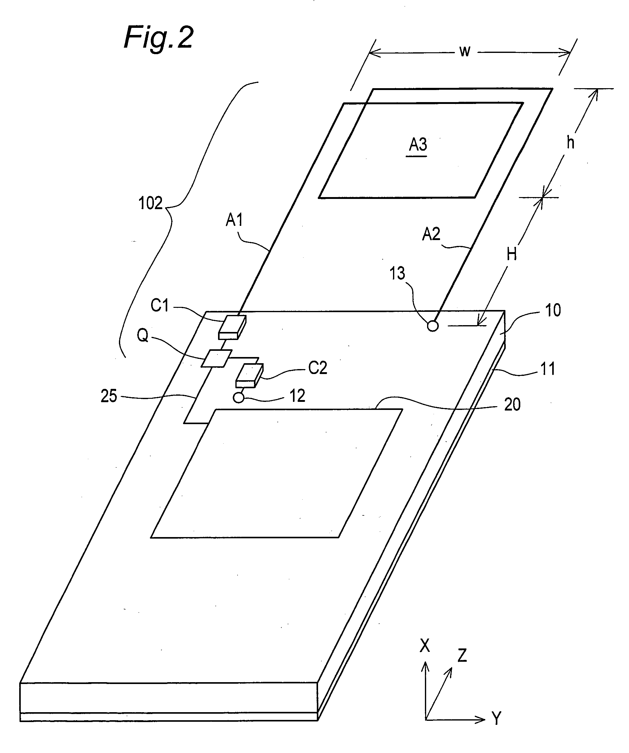
[0111]FIG. 2 is a perspective view showing a configuration of an antenna apparatus 102 according to a second preferred embodiment of the present invention. In FIG. 2, the antenna apparatus 102 according to the second preferred embodiment is characterized, as compared with the antenna apparatus 101 according to the first preferred embodiment, in that a loop axis direction of a minute loop antenna A3 is parallel to the X direction, that is, a loop surface of the minute loop antenna A3 is arranged substantially on the same plane as two antenna elements A1 and A2. In the antenna apparatus 102 as thus constituted, the loop axis direction of the minute loop antenna A3 is parallel to the X direction. In addition, the minute loop antenna A3 effectively operates as a current antenna and has an improved antenna gain for a vertically polarized wave when a metal plate 30 is located apart from the antenna apparatus 102 as described later in detail (See FIG. 14).

third preferred embodiment

[0112]FIG. 3 is a perspective view showing a configuration of an antenna apparatus 103 according to a third preferred embodiment of the present invention. The antenna apparatus 103 according to the third preferred embodiment is characterized, as compared with the antenna apparatus 101 according to the first preferred embodiment, in that a minute loop antenna A3 is arranged so that the loop axis direction of the minute loop antenna A3 is inclined by a predetermined inclination angle θ (03 and an antenna element A1 and that between the minute loop antenna A3 and an antenna element A2. The antenna apparatus 103 as thus constituted operates as a combination of the antenna apparatuses 101 and 102, and have a feature of the operation of the antenna apparatus 101 and that of the antenna apparatus 102. Accordingly, the antenna apparatus 103 can exhibit a directivity characteristic which compensates for disadvantages of the antenna apparatuses 101 and 102, and has an improved integrated ante...


PUM


Abstract

An antenna apparatus includes a minute loop antenna and at least one antenna element. The minute loop antenna is provided to be electromagnetically close to a dielectric substrate including a grounding conductor, has a predetermined number N of turns and a predetermined minute length, operates as a magnetic ideal dipole when a predetermined metal plate is located closely to the antenna apparatus, and operates as a current antenna when the metal plate is located apart from the antenna apparatus. The antenna element is connected to the minute loop antenna, and operates as a current antenna. In the antenna apparatus, one end of the antenna apparatus is connected to a feeding point, and another end of the antenna apparatus is connected to the grounding conductor of the dielectric substrate.

Description

TECHNICAL FIELD [0001] The present invention relates to an antenna apparatus mainly for use in a radio communication apparatus, and also to a radio communication apparatus using the same antenna apparatus. BACKGROUND ART [0002] Conventionally, a loop antenna is used in a portable radio communication apparatus, in particular, a mobile telephone. A configuration of the loop antenna is disclosed in, for example, a prior art document of “Institute of Electronics and Communication Engineers of Japan (IECE) editor, “Antenna Optical Handbook”, pp. 59-63, Ohm-sha Ltd., First Edition, issued on Oct. 30, 1980”. The total length of the loop antenna is normally about one wavelength, a structure of the loop antenna can be approximated to a structure, in which two half wavelength dipole antennas are aligned, based on its current distribution, and the loop antenna operates as a directional antenna having a directivity in a loop axis direction. [0003] When the size of the loop antenna is reduced to...

Claims


Application Information

Patent Timeline
Patent Type & Authority Applications(United States)
IPC IPC(8): H01Q1/24H01Q7/00H01Q3/24H01Q9/36H01Q21/24H04B1/38H04B1/3822
CPCH01Q1/24H01Q7/00H01Q9/36H01Q21/24H01Q1/243
Inventor YOSHIKAWA, YOSHISHIGEHORIIKE, YOSHIOYOKOAJIRO, YOSHIYUKIMATSUMOTO, TAKAYUKI
Owner PANASONIC CORP
Why Eureka
Try Eureka