Wiring harness and touch sensor incorporating same

a technology of wiring harness and touch sensor, applied in the field of sensing devices, can solve the problems of laborious connection of individual wires to the touch panel, damage to the panel, and rendering the touch panel inoperabl

Inactive Publication Date: 2005-06-16
3M INNOVATIVE PROPERTIES CO
View PDF15 Cites 122 Cited by
  • Summary
  • Abstract
  • Description
  • Claims
  • Application Information

AI Technical Summary

Problems solved by technology

Connecting individual wires to the touch panel is labor intensive, usually done by hand, an

Method used


Image

  • Wiring harness and touch sensor incorporating same
  • Wiring harness and touch sensor incorporating same
  • Wiring harness and touch sensor incorporating same

Examples


Embodiment Construction

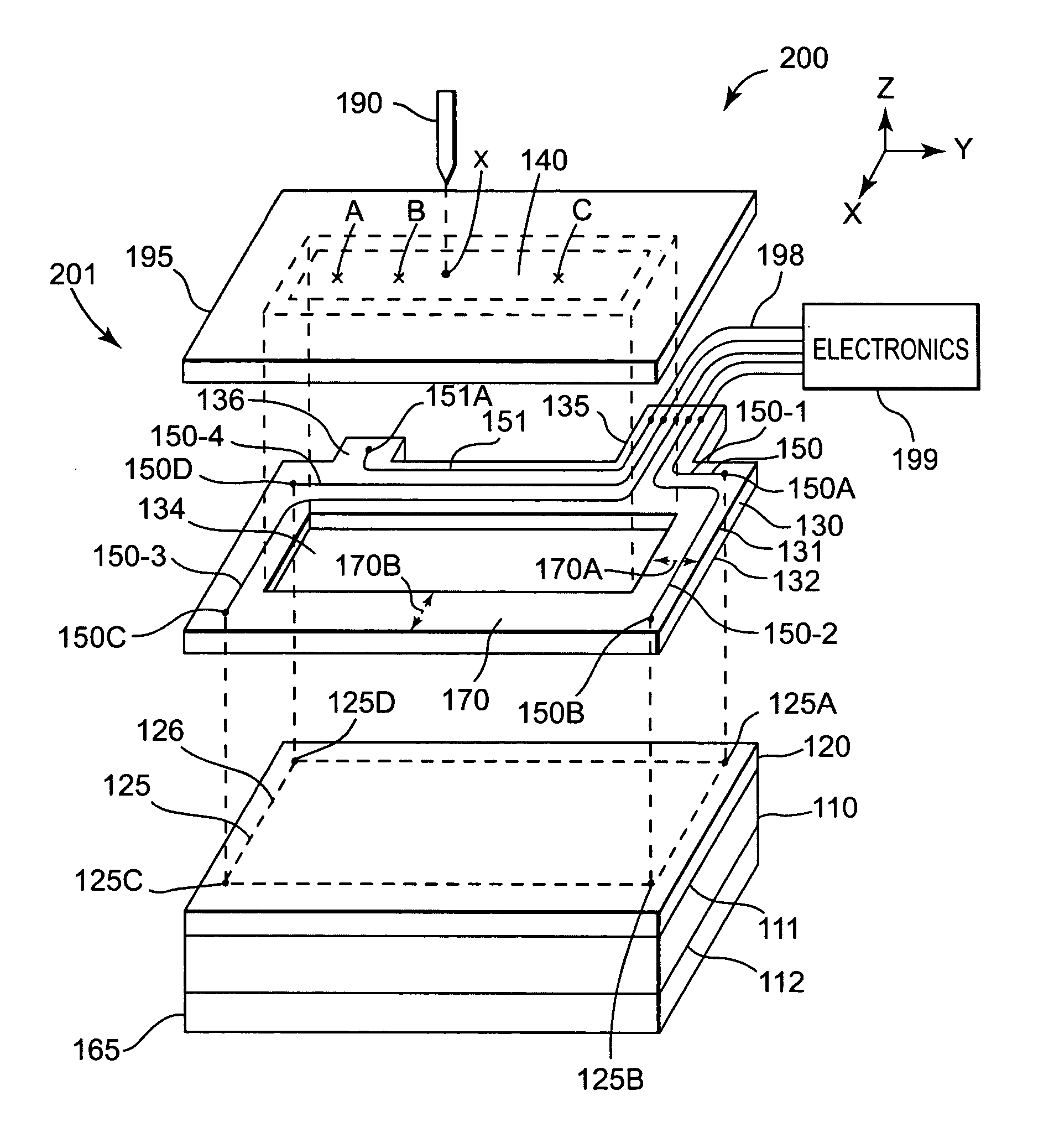
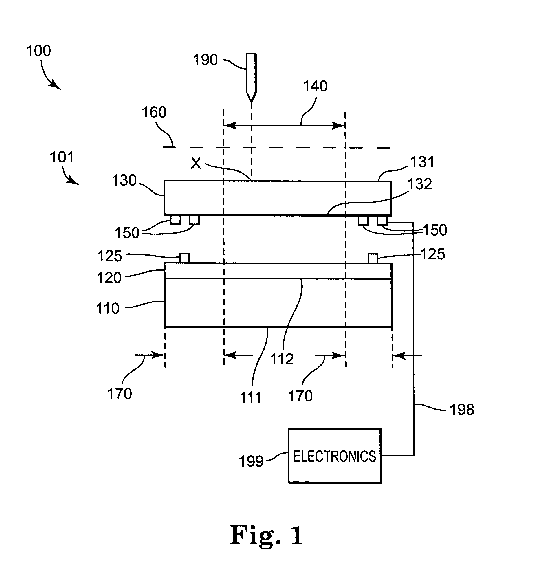
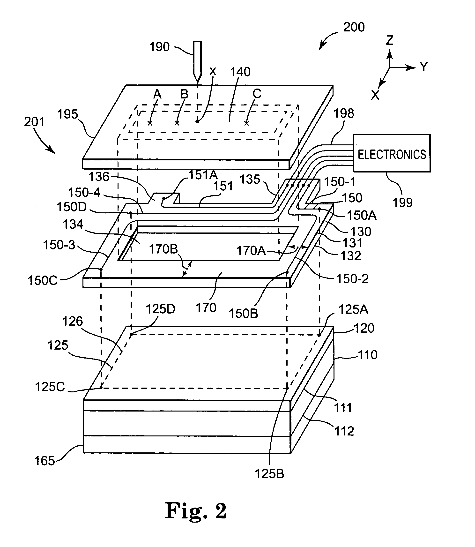
[0018] The present invention generally relates to touch sensors. The invention is particularly applicable to touch sensors having an integral wiring harness, and even more particularly to capacitive and resistive touch sensors having an integral wiring harness.

[0019] A touch screen functions on the general principle that an otherwise open electrical circuit is closed when a touch is applied. The properties of a signal generated in the closed circuit allows detection of a touch location. Various technologies may be employed to detect a touch location. One such technology is resistive. In a resistive touch, an applied touch brings two otherwise physically separated conductive films into direct physical contact with one another. The physical contact closes an otherwise open electronic circuit, thereby resulting in generation of a resistively coupled electrical signal. The properties of the generated signal allow detection of the touch location.

[0020] Capacitive is a technology common...


PUM


Abstract

A wiring harness and a touch sensor incorporating same are disclosed. The touch sensor includes a sensing electrode disposed in a touch sensitive area. The touch sensor further includes a plurality of auxiliary electrodes disposed on a self-supporting dielectric substrate in a border area. The auxiliary electrodes transmit a touch signal to electronics configured to use the touch signal to determine the touch location.

Description

RELATED APPLICATIONS [0001] This application is related to application Ser. No. 10 / 679,903 filed Oct. 6, 2003 entitled TOUCH INPUT SENSING DEVICE.FIELD OF THE INVENTION [0002] This invention generally relates to sensing devices. The invention is particularly applicable to touch sensors having a wiring harness integral to the touch panel. BACKGROUND [0003] Touch screens allow a user to conveniently interface with an electronic display system by reducing or eliminating the need for a keyboard. For example, a user can carry out a complicated sequence of instructions by simply touching the screen at a location identified by a pre-programmed icon. The on-screen menu may be changed by re-programming the supporting software according to the application. As another example, a touch screen may allow a user to transfer text or drawings to an electronic display device by directly writing or drawing onto the touch screen. [0004] Resistive and capacitive are two common touch sensing methods empl...

Claims


Application Information

Patent Timeline
IPC IPC(8): G06F3/033G06F3/044G06F3/045
CPCG06F3/045G06F3/044G06F3/0444G06F3/0416
Inventor RICHTER, PAUL J.CAIRNS, DARRAN R.BOTTARI, FRANK J.
Owner 3M INNOVATIVE PROPERTIES CO
Why Eureka
Try Eureka