Substrate integrated waveguide antenna array

a waveguide antenna and integrated technology, applied in the field of antennas, can solve the problems of unacceptable cross-polarization level, significant gain drop, unacceptable overall antenna height, etc., and achieve the effect of reducing the overall height and physical steering requirements of a mobile antenna

Inactive Publication Date: 2010-10-05
UNIV OF TENNESSEE RES FOUND
View PDF6 Cites 124 Cited by
  • Summary
  • Abstract
  • Description
  • Claims
  • Application Information

AI Technical Summary

Benefits of technology

[0010]A substrate integrated waveguide (SIW) slot full-array antenna fabricated employing printed circuit board technology. The SIW slot full-array antenna using either single or multi-layer structures greatly reduces the overall height and physical steering requirements of a mobile antenna when compared to a conventional metallic waveguide slot array antenna. The SIW slot full-array antenna is fabricated using a low-loss dielectric substrate with top and bottom metal plating. An array of radiating cross-slots is etched in to the top plating to produce circular polarization at a selected tilt-angle. Lines of spaced-apart, metal-lined vias form the sidewalls of the waveguides and feeding network. In multi-layer structures, the adjoining layers are coupled by transverse slots at the interface of the two layers.

Problems solved by technology

At this angle, the gain drops significantly and the cross-polarization level becomes unacceptably high.
However, the large scanning volume of the mechanically-steered antennas produces an unacceptable overall antenna height.
However, these designs suffered from the prohibiting cost of manufacturing, as well their heavy weight.
One previous development was the design and fabrication of an all-metallic array, which was very expensive and heavy to produce.

Method used


Image

  • Substrate integrated waveguide antenna array
  • Substrate integrated waveguide antenna array
  • Substrate integrated waveguide antenna array

Examples


Embodiment Construction

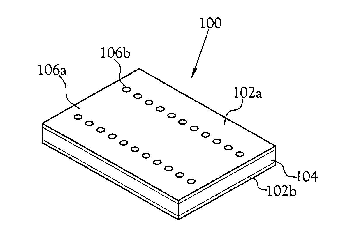
[0075]A low-profile, steerable antenna is shown and described herein. The low-profile, steerable antenna is a leaky-wave slot-array antenna radiating at an inherent tilt angle, which reduces the scan volume requirements significantly. The leaky-wave slot-array antenna uses printed circuit substrates using substrate integrated waveguide (SIW) technology.

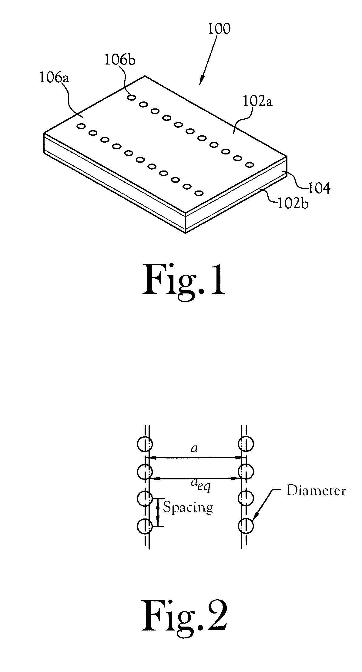
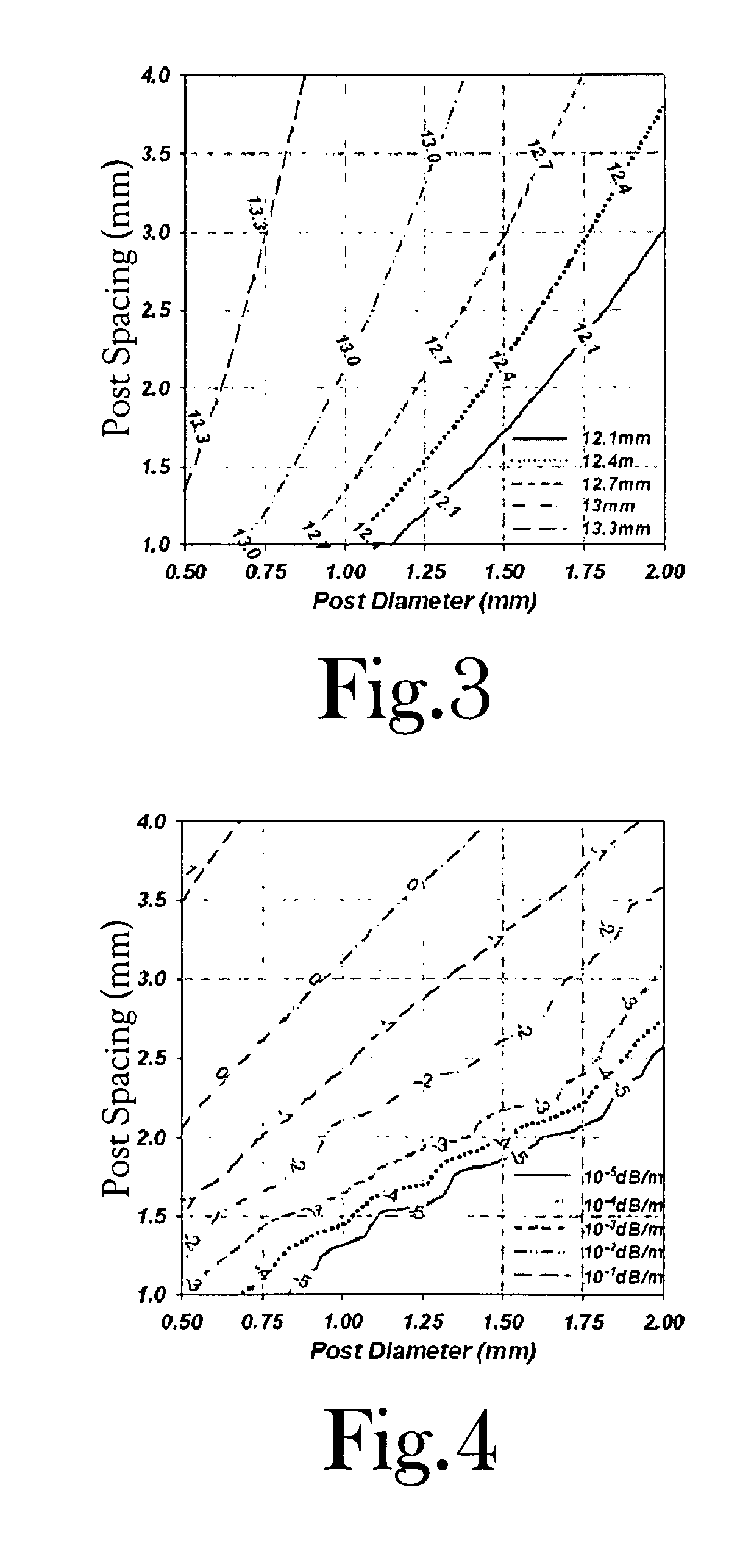
[0076]Conventionally, both the slot-array antennas and their associated feed networks are fabricated using metallic waveguides due to the extremely low loss performance. However, metallic waveguide slot array antennas are bulky, heavy, and expensive to fabricate. In order to extend the well-known design rules of the metallic waveguide slot arrays to SIW designs, the present inventors have extensively studied the parameters of SIW structures, including the use of Ansoft HFSS™ to develop an equivalent conventional dielectrically-loaded waveguide to represent the SIW structure and perform a full-wave 3D analysis. This equivalent structur...


PUM


Abstract

A substrate integrated waveguide (SIW) slot full-array antenna fabricated employing printed circuit board technology. The SIW slot full-array antenna using either single or multi-layer structures greatly reduces the overall height and physical steering requirements of a mobile antenna when compared to a conventional metallic waveguide slot array antenna. The SIW slot full-array antenna is fabricated using a low-loss dielectric substrate with top and bottom metal plating. An array of radiating cross-slots is etched in to the top plating to produce circular polarization at a selected tilt-angle. Lines of spaced-apart, metal-lined vias form the sidewalls of the waveguides and feeding network. In multi-layer structures, the adjoining layers are coupled by transverse slots at the interface of the two layers.

Description

CROSS-REFERENCE TO RELATED APPLICATIONS[0001]This application claims the benefit of U.S. Provisional Application No. 60 / 970,551 filed Sep. 7, 2007.STATEMENT REGARDING FEDERALLY SPONSORED RESEARCH OR DEVELOPMENT[0002]Not ApplicableBACKGROUND OF THE INVENTION[0003]1. Field of Invention[0004]The present invention pertains to the field of antennas used in communications. Particularly, this invention is related to a substrate integrated waveguide (SIW) antenna array for use in communications including, but not limited to, mobile direct broadcast satellite reception.[0005]2. Description of the Related Art[0006]The basic antenna requirements for mobile direct broadcast satellite (DBS) reception in the United States include: (1) dual circular polarization, (2) a gain of approximately 32 dBi, and (3) full steering in two planes for satellite tracking with a 360° steering range in the azimuth and a 50° steering range in the elevation from 20° to 70° above horizon. When using a flat-plate phas...

Claims


Application Information

Patent Timeline
Patent Type & Authority Patents(United States)
IPC IPC(8): H01Q13/10
CPCH01P3/121H01Q13/22H01Q21/005
Inventor YANG, SONGNANFATHY, ALY E.
Owner UNIV OF TENNESSEE RES FOUND
Why Eureka
Try Eureka