
Knee pad constructions

a knee pad and construction technology, applied in the field of protective knee pads, can solve the problems of not being able to meet the needs of all workers, the pad will tend to slip or move, and is considered vexing to various workmen and others who need to wear protective knee pads

Inactive Publication Date: 2010-11-30
BIG TIME PROD LLC
View PDF53 Cites 15 Cited by
  • Summary
  • Abstract
  • Description
  • Claims
  • Application Information

AI Technical Summary

Benefits of technology

[0007]Briefly, the present invention comprises a knee pad construction which includes a first shell designed to fit over and protect the patella or knee of a workman. The first shell is coupled to a second member such as a strap or other construct, which is designed to engage or fit on the thigh of a workman and simultaneously be connected to or joined to the first shell shaped knee pad section. The combination of the protective first knee shell and the second thigh member provide extra protection for the user of the knee pad. The two elements or members, namely the knee pad for the protection of the knee and the thigh member, are hinged together and thus may articulate one with respect to the other.
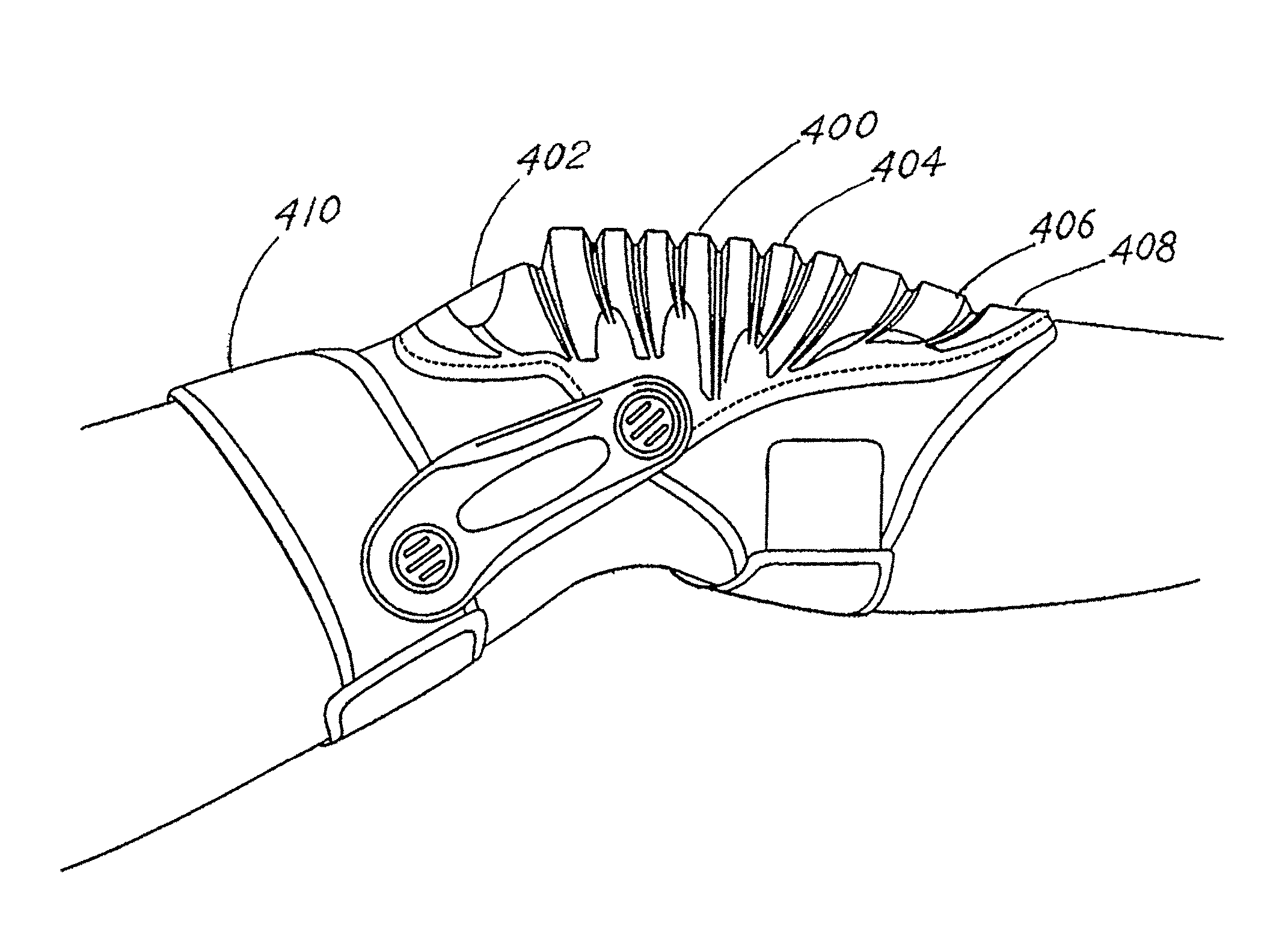
[0009]Straps are used to attach each of the described member elements of the knee pad assembly to the appropriate portion of a leg of a workman or individual using the knee pads. The knee pad shell, or portion of the device which protects the knee or patella, is typically convex in shape with the interior side being relatively concave so as to comfortably fit over the knee of an individual. The interior is typically padded. The exterior of the knee shell may be fabricated in a number of forms. Thus, it may include a flat or ribbed surface to facilitate balance by the user of the knee pads. Most typically, the exterior surface is formed from a hard polymeric material or hard rubber or similar material and the surface thereof is generally flat or includes an appropriate shape and pattern of ribs to facilitate balance and utility by the workman.
[0010]Thus, it is an object of the invention to provide improved knee pad constructions.
[0012]Another object of the invention is to provide a knee pad construction which will facilitate simultaneous protection of the lower thigh, the knee and the upper shin of a workman or user.
[0013]Another object of the invention is to provide a knee pad construction wherein a thigh member fitted over the lower thigh is attached to and articulates with respect to a knee pad construct that covers and protects the knee.
[0014]A further object of the invention is to provide a knee pad construction which is rugged, economical, easy to use, lightweight and capable of use for protection of a wide variety of knee sizes and shapes.

Problems solved by technology

One problem associated with the use of knee pads relates to a situation where the pad will tend to slip or move while the workman or individual using the pad is changing positions; for example, moving from a standing to a kneeling position.
While such solutions have their benefits, they are not necessarily acceptable in all circumstances.
Another problem often observed with protective knee pads for workman and others is associated with the shape or form of the knee pad.
These, among other issues, have been considered vexing to various workman and others needing protective knee pads.

Method used


Image

  • Knee pad constructions
  • Knee pad constructions
  • Knee pad constructions

Examples


Embodiment Construction

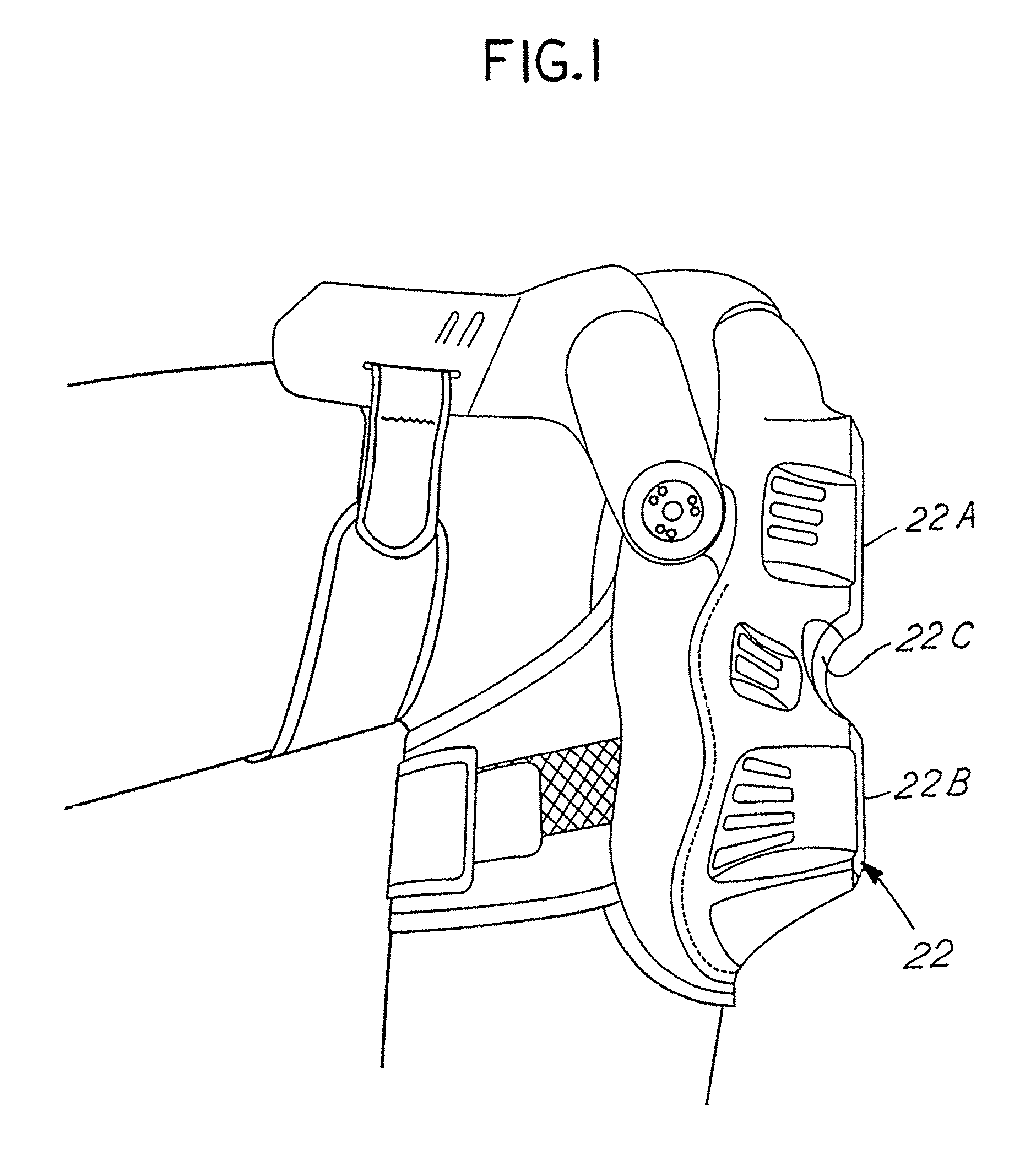
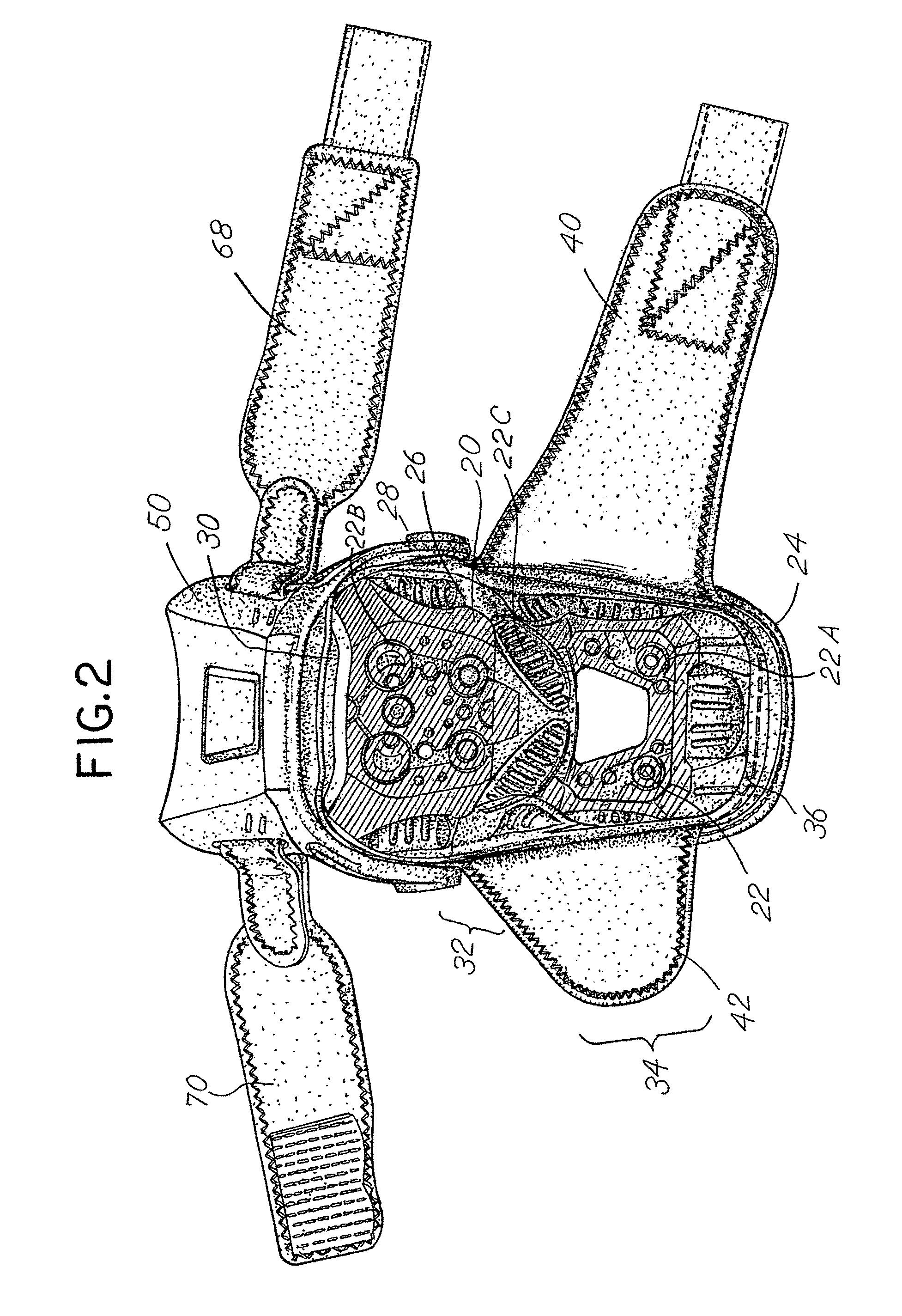
[0064]FIGS. 1-4 illustrate features associated with a first embodiment of the invention. The embodiment of FIGS. 1-4 comprises a protective knee pad which includes a first generally rigid, formed knee protection shell 20. The shell 20 includes an outer face 22. It further includes a peripheral edge 24, an inner concave section 26 with layer padding 27 with an optional gel insert 28. The hard shell 20 includes an upper section or end 30, a mid section 32 and a lower section or end 34. The upper side or end 30 is designed to fit over the top of a knee or patella. The mid-section 32 fits directly over the patella. The lower section 34 fits over the upper shin of an individual. The lower end or section 34 is generally cylindrical in shape and the extreme lower end extends outwardly and upwardly away from the shin in the manner of a duck bill 36.

[0065]The outer face 22 may have any number of desired forms. It may be generally convex. It may include a surface comprised of various flat sec...


PUM


Abstract

Protective knee pads are comprised of a first shell member which fits over the patella and knee joint and a second member which is attached to the lower thigh and pivotally engaged with the knee pad shell so that they may articulate one with respect to the other while providing additional support and protection for the user of the knee pad. An additional shin pad may also be attached to the lower end of the shell which covers the knee.

Description

CROSS REFERENCE TO RELATED APPLICATIONS[0001]This is a continuation in part application of Ser. No. 11 / 679,021 filed Feb. 26, 2007 entitled “Knee Pad Constructions” which is a continuation in part application of Ser. No. 11 / 670,297, filed Feb. 1, 2007, entitled “Knee Pad Construction” which is a continuation in part application of Ser. No. 10 / 943,347, filed Sep. 17, 2004, now U.S. Pat. No. 7,376,978 entitled “Knee Pad Construction” which is a continuation in part application of Ser. No. 10 / 926,240, filed Aug. 25, 2004, entitled “Knee Pad Construction”, now U.S. Pat. No. 7,181,770 issued Feb. 27, 2007, each of which is incorporated herewith by reference and for which priority is claimed.BACKGROUND OF THE INVENTION[0002]In a principal aspect, the present invention relates to protective knee pad constructions and, more particularly, to pairs of knee pads for workmen which are constructed to cover and protect the lower thigh, knee and upper shin of a workman.[0003]Protective knee pads a...

Claims


Application Information

Patent Timeline
Patent Type & Authority Patents(United States)
IPC IPC(8): A41D13/00
CPCA41D13/065A41D13/0153A41D13/00
Inventor GODSHAW, DONALD E.REDZISZ, ANDREZJ M.HAI, DUSCHANTZ, BRAD LEE
Owner BIG TIME PROD LLC
Learn More