Small vehicle with power steering assembly

a technology of power steering and small vehicles, applied in electrical steering, transportation and packaging, bicycles, etc., can solve the problems of physical tiring steering of vehicles, affecting the steering characteristics of vehicles, and unable to steer without forward or rearward movement, so as to avoid interference with shock absorbers

Inactive Publication Date: 2005-11-22
YAMAHA MOTOR CO LTD
View PDF44 Cites 62 Cited by
  • Summary
  • Abstract
  • Description
  • Claims
  • Application Information

AI Technical Summary

Benefits of technology

[0013]Thus, an arrangement is desired in which the power steering driving motor can be adequately protected from road debris and engine exhaust heat while avoiding interference with the shock absorbers.

Problems solved by technology

During operation, the vehicle can be physically tiring to steer.
For instance, as size and complexity of these vehicles has increased, steering the vehicle without forward or rearward movement has become more difficult because of the weight supported by the steered wheels.
In addition, the vehicle often traverses fairly large obstacles, which can affect the steering characteristics of the vehicle.
While positioning the power steering driving motor on an all terrain vehicle parallel to and behind the steering shaft is possible, such a configuration suffers from several disadvantages.
For example, this configuration renders the power steering driving motor particularly vulnerable to objects thrown up from the operating surface, such as stones or other debris.
Additionally, this configuration subjects the power steering driving motor to a potentially damaging amount of exhaust heat from the engine because most engines are mounted just rearward of the steering shaft with an exhaust system that wraps rearward from a forward surface of the engine.
Moreover, in this configuration the power steering driving motor is immediately adjacent to the shock absorbers, and thus can potentially interfere with the operation of the shock absorbers.

Method used


Image

  • Small vehicle with power steering assembly
  • Small vehicle with power steering assembly
  • Small vehicle with power steering assembly

Examples


Embodiment Construction

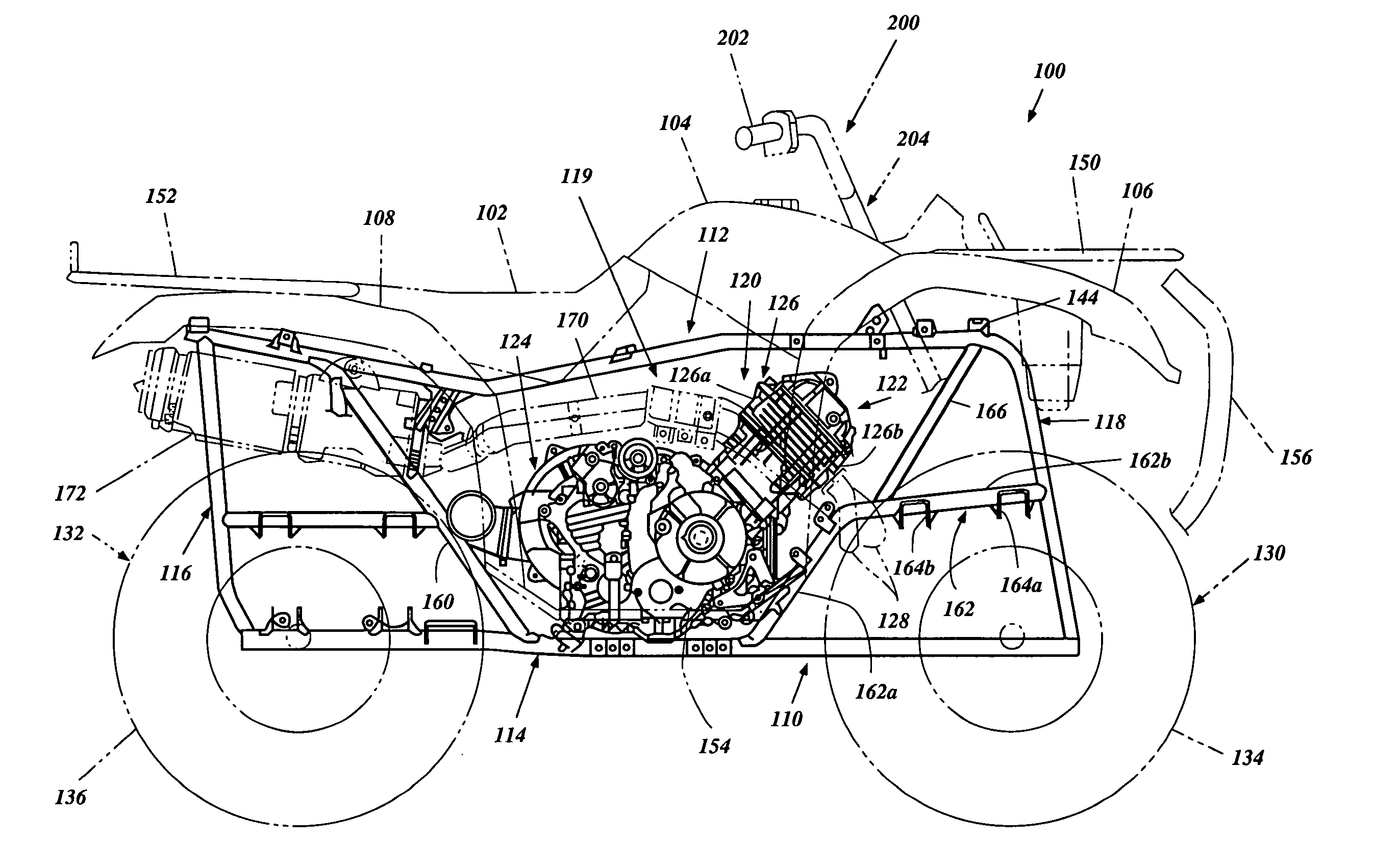
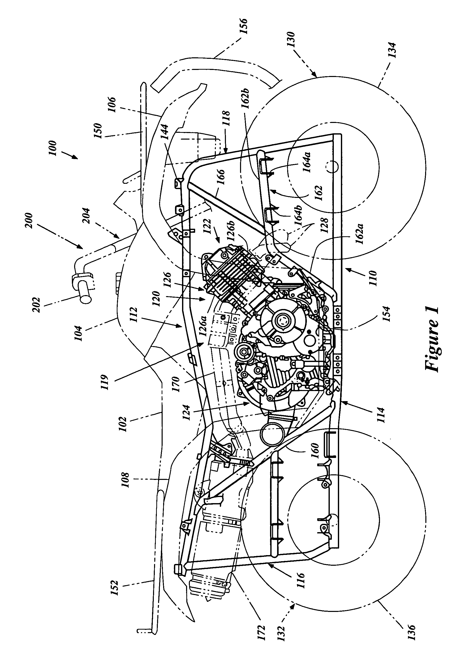
[0024]With reference initially to FIG. 1, a small all terrain vehicle 100 is illustrated. The vehicle 100 is arranged and configured in accordance with certain feature, aspects and advantages of the present invention. While the present invention will be described in the context of a small all terrain vehicle, other vehicles also may benefit form certain features, aspects and advantages of the present invention. For instance, vehicles having an exposed steering system (e.g., snowmobiles, lawn mowers, go-carts, etc.) may benefit from certain features, aspects and advantages of the present invention.

[0025]The vehicle 100 comprises a frame assembly 110. The frame assembly 110 can have any suitable construction. In one arrangement, the frame assembly 110 is configured to be a “double-cradle” type. In the illustrated arrangement, the frame assembly 110 comprises left and right side frame subassemblies each having a generally rectangular shape. Each of the illustrated subassemblies compris...


PUM


Abstract

An all terrain vehicle has a pair of front wheels that support a frame assembly. An engine is supported by the frame assembly and a steering column is supported by the frame assembly at a location generally forward of the engine. A set of handlebars are connected to an upper portion of the steering column and a lower portion of the steering column is operatively connected to the pair of front wheels. A power steering assembly is disposed along a portion of the steering column. The power steering assembly is operatively connected to the steering column. The power steering assembly comprises a motor having a longitudinal axis that extends in a generally lateral direction and at least a portion of the motor overlies a portion of the frame assembly.

Description

BACKGROUND OF THE INVENTION[0001]1. Field of the Invention[0002]The present invention generally relates to a power steering assembly adapted for use in a small all terrain vehicle. More specifically, the present invention relates to such a power steering assembly configured, oriented and positioned for use with a small all terrain vehicle.[0003]2. Description of the Related Art[0004]Small all terrain vehicles generally comprise a frame assembly that is carried by three or more wheels. Recent constructions of these vehicles feature a pair of front wheels that are steerable relative to the frame and a pair of rear wheels. An engine generally is mounted between the front wheels and the rear wheels because the frame assembly is narrowly constructed. The engine powers the rear wheels and, in some arrangements, the front wheels through suitable transmissions.[0005]The engine generally comprises one or more combustion chambers that are partially defined by a cylinder block, a cylinder head...

Claims


Application Information

Patent Timeline
Patent Type & Authority Patents(United States)
IPC IPC(8): B62D5/04
CPCB62D5/0421Y10S180/908
Inventor TANIGAKI, SATOSHINOMURA, TOSHIAKI
Owner YAMAHA MOTOR CO LTD
Why Eureka
Try Eureka