LED lighting assembly and lamp utilizing same

a technology of led lamps and lighting assemblies, applied in the field of light transmission media and to lighting assemblies and lamps, can solve the problems of shortening the useful life of led lamps, affecting the health of persons exposed to such lighting sources, and requiring replacements. the effect of 100,000 hours

a technology of led lamps and lighting assemblies, applied in the field of light transmission media and to lighting assemblies and lamps, can solve the problems of shortening the useful life of led lamps, affecting the health of persons exposed to such lighting sources, and requiring replacements. the effect of 100,000 hours

US7841741B2Inactive Publication Date: 2010-11-30TTM TECH NORTH AMERICA LLC

Image

  • LED lighting assembly and lamp utilizing same
  • LED lighting assembly and lamp utilizing same
  • LED lighting assembly and lamp utilizing same

Examples


Embodiment Construction

[0062]For a better understanding of the present invention, together with other and further objects, advantages and capabilities thereof, reference is made to the following disclosure and appended claims in connection with the above-described drawings. Like figure numbers will be used from figure to figure to identify like elements in these drawings.

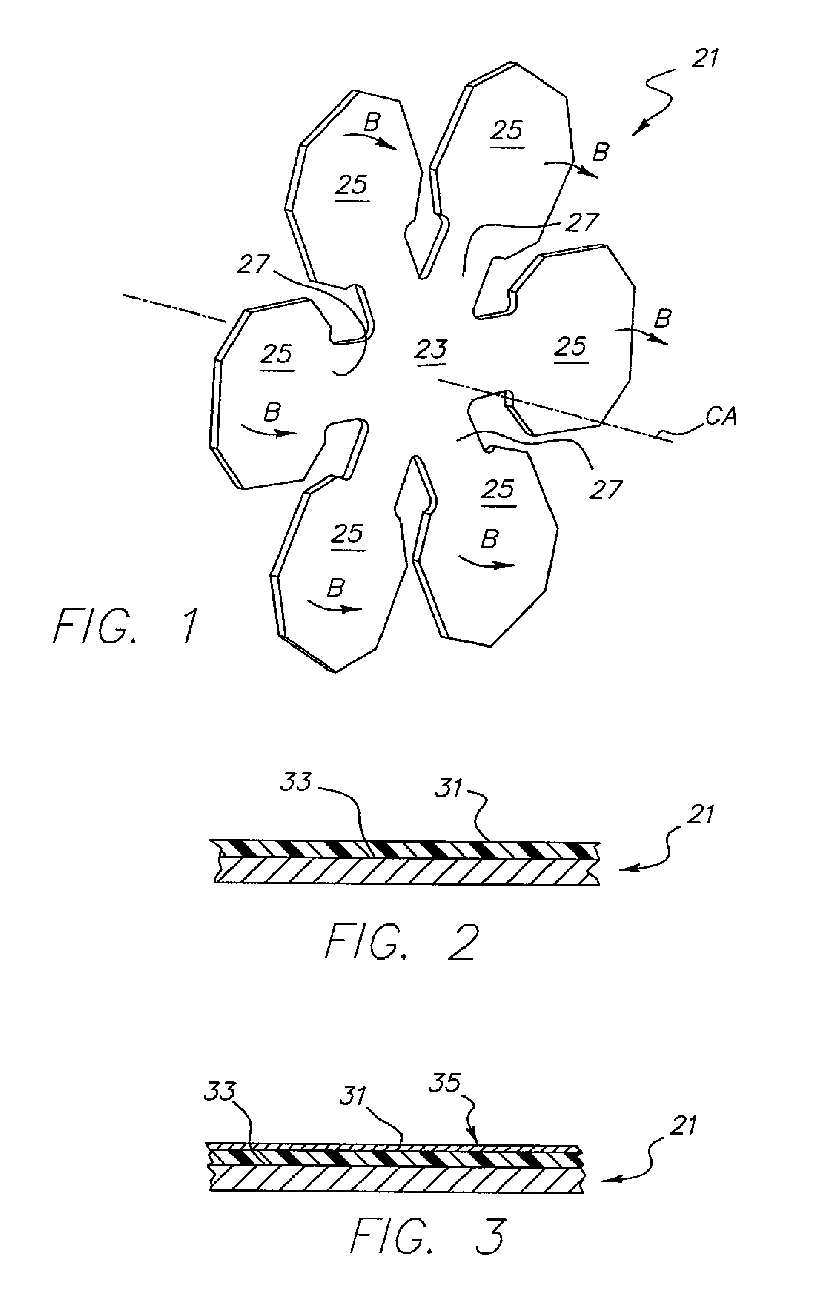
[0063]In FIG. 1, there is shown a bendable thermally conductive member 21 according to one embodiment of the invention, member 21 being adapted for forming part of an LED lighting assembly (defined in greater detail herein-below). Member 21 includes a substantially central portion 23 surrounded by a plurality of bendable projecting “wing” portions 25, these wing portions arranged in a substantially annular pattern about the substantially central portion 23. In one embodiment (as shown), a total of six “wing” portions 25 are provided. It is understood however, that the invention is not limited to using six because other numbers of such por...


PUM


Abstract

An LED lighting assembly including a plurality of individual LEDs mounted on a common, bendable heat sinking member designed to remove heat from the LEDs during operation and also to be formed (bent) to provide the desired light direction and intensity. Several such assemblies may be used within an LED lamp, as also provided herein. The lamp is ideal for use within medical and dental environments to assure optimal light onto a patient located at a specified distance from the lamp.

Description

TECHNICAL FIELD[0001]The present invention relates broadly to light transmission media and to lighting assemblies and lamps for providing such light transmission. More particularly, this invention relates to improvements in such lighting assemblies and lamps which incorporate light emitting diodes as light sources. Even more particularly, the invention relates to such assemblies and lamps which may be utilized in a highly demanding environment such as the medical field, e.g., for use in surgery or dentistry.BACKGROUND OF THE INVENTION[0002]LEDs (light emitting diodes) have been used for various lighting purposes for many years, including, for example, as indicator lights and in arrays to form information displays. An LED is essentially a PN junction semiconductor diode that emits light when a current is applied thereto. The LED is a solid state device which operates at a low current and, as a single unit, produces negligible heat. It is typically encapsulated in a resin material whi...

Claims


Application Information

Patent Timeline
30 Nov 2010
Publication
US7841741B2
IPC
F21S4/00
CPC
F21S48/328; F21V29/004; F21V29/85; H05K1/189; H05K3/284; F21K9/00; F21W2131/202; F21Y2101/02
Inventors
CHAN, BENSON; KOZOL, JOHN E.