Chemical liquid supplying apparatus

a technology of liquid supply apparatus and liquid supply, which is applied in the direction of positive displacement liquid engine, pump, machine/engine, etc., can solve the problems of lower application of incompressible medium in the bellows type, inability to discharge chemical liquid with high accuracy, wear of seal parts, etc., and achieve the effect of determining the degree of sealing property more accurately

Inactive Publication Date: 2010-11-30
KOGANEI
View PDF17 Cites 6 Cited by
  • Summary
  • Abstract
  • Description
  • Claims
  • Application Information

AI Technical Summary

Benefits of technology

[0009]Contrary to this, since the pump of the above-mentioned bellows type does not use the seal member contacting with the sliding face, there is the advantage that airtight properties of the drive chamber filled with the incompressible medium and the pump chamber pressurizing the chemical liquid are high. However, there is a tendency to the fact that pressure applied to the incompressible medium in the bellows type is lower than that in the syringe type. For example, when resist is discharged to the nozzle through a filter, since flow resistance of the filter is high, the pressure in the pump chamber needs to be increased. Consequently, when the bellows is driven, the pressure of the incompressible medium in the drive chamber becomes high, so that the bellows may be expanded slightly radially. At this time, if the bellows is expanded, a movement stroke of the bellows results in not corresponding to the discharge amount of chemical liquid with high accuracy.
[0010]The pump of the above-mentioned syringe type is preferred to increase discharge pressure of the pump. However, as wear of the seal member progresses, the incompressible medium in the drive chamber results in leaking to the outside. Thus, the seal member may be replaced periodically. Similarly also in a chemical-liquid discharge pump of a type of preventing a leakage of the incompressible medium in the drive chamber by narrowing a gap between the outer peripheral surface of the piston and the inner peripheral surface of the cylinder, as the wear of the sliding face between the piston and the cylinder progresses, the incompressible medium in the drive chamber leaks to the outside, so that the piston and the cylinder need to be replaced.
[0012]An object of the present invention is to provide a chemical liquid supplying apparatus which can monitor any leakage of the incompressible medium in the drive chamber from the gap between the piston and the cylinder.
[0013]Another object of the present invention is to provide a chemical liquid supplying apparatus which can determine lifetime by an amount of leakage of the incompressible medium in the drive chamber.
[0019]The first seal chamber continuous to the sliding face between the piston and the cylinder is formed by the elastic deformable member such as a bellows cover provided between the piston and the cylinder, and the second seal chamber communicating with the first seal chamber is formed by the elastic deformable member, wherein the incompressible medium is enclosed in each of the seal chambers. Thus, since the elastic deformable member for forming the seal chamber(s) has no sliding portion, the leakage of the incompressible medium from the elastic deformable member can be prevented completely. Therefore, even if the incompressible medium enclosed inside leaks from a region between the sliding face of the piston and the sliding face of the cylinder by pressurizing the drive chamber using the piston, the incompressible medium flows into the seal chamber, so that the leakage of the incompressible medium to an exterior of the apparatus is prevented.
[0022]By detecting the pressure in the seal chamber and the pressure in the drive chamber, the deterioration degree of the sealing property can be determined more accurately in view of an influence of the pressure change of the seal chamber due to the pressure change of the drive chamber.

Problems solved by technology

That is, if air enters into the incompressible medium from the outside, incompressibility of the incompressible medium is macroscopically lost, so that motion of the bellows or piston cannot be accurately transmitted to the diaphragm or tube and a movement stroke of the bellows or piston results in not corresponding to a discharge amount of chemical liquid.
Further, similarly thereto, also when the incompressible medium leaks out, the movement stroke of the bellows results in not corresponding to the discharge amount of chemical liquid, so that the chemical liquid cannot be discharged with high accuracy.
Consequently, the seal member directly contacts with the outer peripheral surface of the piston, whereby wear of the seal member progresses.
However, there is a tendency to the fact that pressure applied to the incompressible medium in the bellows type is lower than that in the syringe type.

Method used


Image

  • Chemical liquid supplying apparatus
  • Chemical liquid supplying apparatus
  • Chemical liquid supplying apparatus

Examples


Embodiment Construction

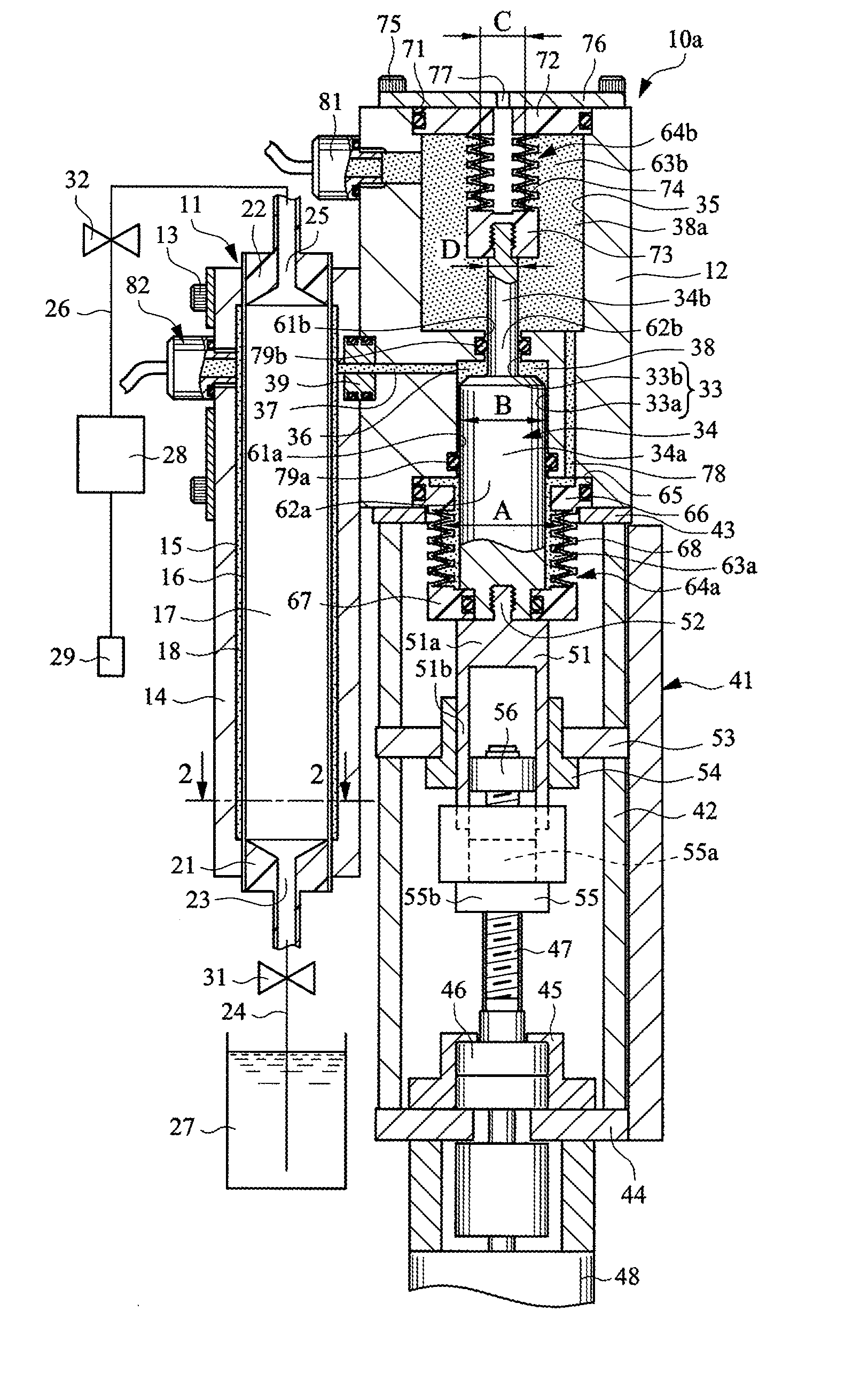
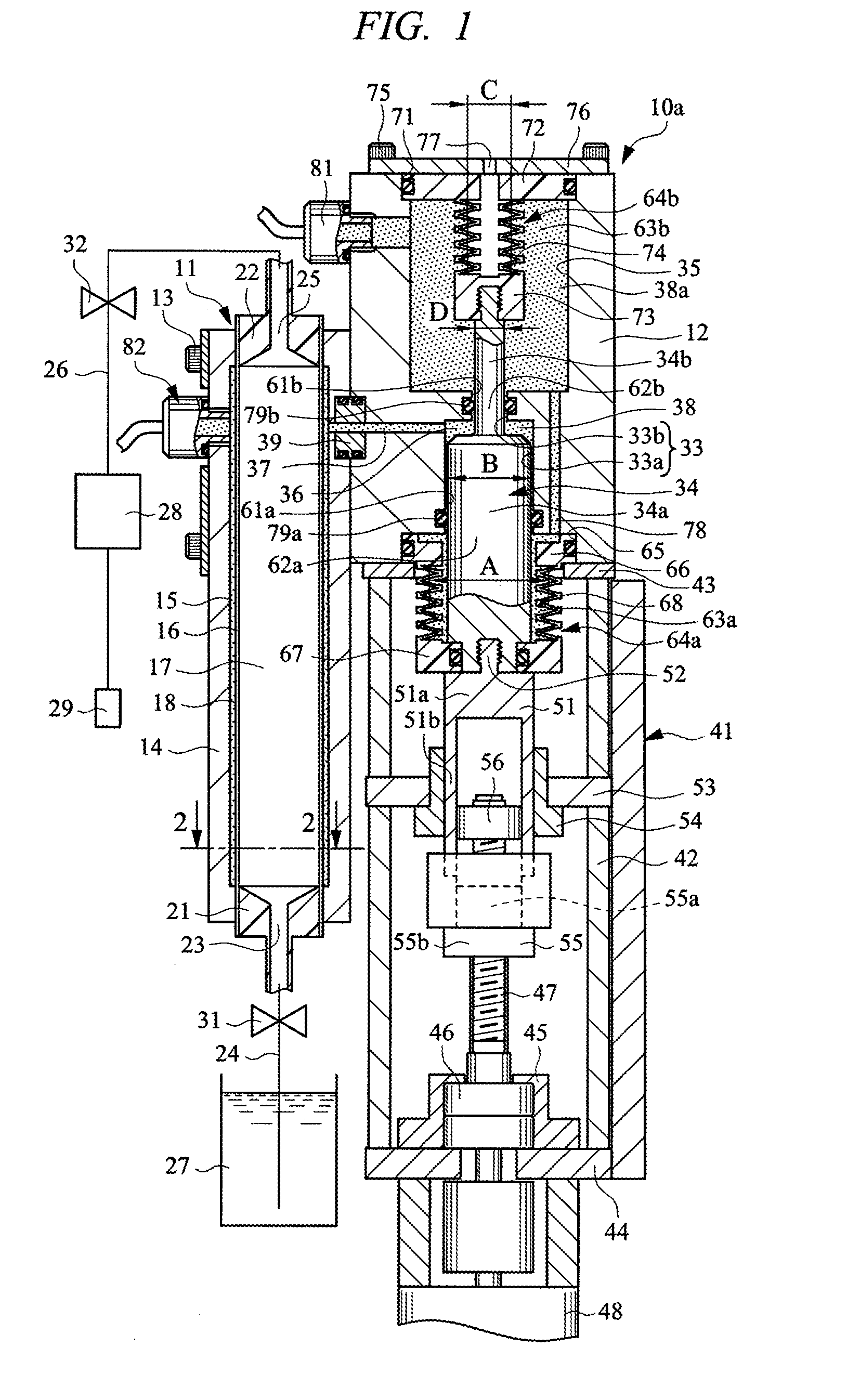
[0038]Hereinafter, embodiments of the present invention will be described in detail with reference to the drawings. FIG. 1 is a sectional view showing a chemical liquid supplying apparatus according to an embodiment of the present invention.

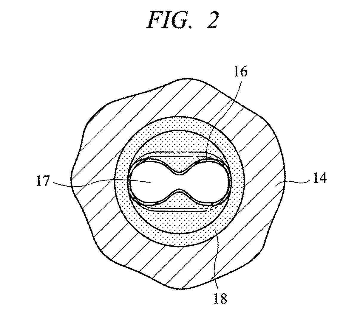
[0039]This chemical liquid supplying apparatus 10a comprises a pump 11 and a cylinder 12. The pump 11 has a pump case 14 fixed to the cylinder 12 by bolts 13, and a flexible tube 16 attached within a cylindrical space 15 in the pump case 14. The flexible tube 16 is formed of a radially expandable / contractable elastic member, and the space 15 is partitioned by the flexible tube 16 into a pump chamber 17 located inside the flexible tube and a pump-side drive chamber 18 located outside the flexible tube, so that the flexible tube 16 constitutes a partition film.

[0040]Adaptor portions 21 and 22 are attached on both end portions of the flexible tube 16. A liquid inflow port 23 communicating with the pump chamber 17 is formed on the adapter portion 21 ...


PUM


Abstract

A chemical liquid supplying apparatus capable of discharging chemical liquid with high accuracy and monitoring a leakage of an incompressible medium from a region between a piston and a cylinder is provided. A pump has a flexible tube for partitioning a pump chamber and a drive chamber, and the incompressible medium is supplied to the drive chamber by the piston reciprocating within a cylinder hole of the cylinder. A first bellows cover for forming a first seal chamber is provided between a large-diameter piston portion and the cylinder, and a second bellows cover for forming a second seal chamber is provided between a small-diameter piston portion and the cylinder. To detect pressure of the incompressible medium enclosed in the seal chambers, a seal-chamber pressure sensor is attached to the cylinder, and a deterioration degree of seal members is determined by detecting the pressure.

Description

CROSS-REFERENCE TO RELATED APPLICATIONS[0001]Applicant hereby claims foreign priority benefits under U.S.C. §119 from Japanese Patent Application No. 2006-322235 filed on Nov. 29, 2006, the contents of which are incorporated by reference herein.TECHNICAL FIELD OF THE INVENTION[0002]The present invention relates to a chemical liquid supplying apparatus which discharges a predetermined amount of chemical liquid such as photoresist liquid.BACKGROUND OF THE INVENTION[0003]A fine circuit pattern is produced on a surface of a semiconductor wafer or liquid crystal glass substrate by a photolithography process and an etching process. In the photolithography process, a chemical liquid supplying apparatus has been used to apply chemical liquid such as photoresist liquid to a surface of wafer or glass substrate, and the chemical liquid accommodated in a container is sucked up by a pump, passes through a filter or the like, and is applied to an object to be applied such as a wafer from a nozzle...

Claims


Application Information

Patent Timeline
Patent Type & Authority Patents(United States)
IPC IPC(8): F04B43/10F04B45/00
CPCF04B43/107G03F7/2041G03F7/70341G03F7/70808H01L21/02019H01L21/0274
Inventor YAJIMA, TAKEO
Owner KOGANEI
Why Eureka
Try Eureka