Optical transceiver with reduced height

a transceiver and optical technology, applied in electromagnetic transceivers, counting objects on conveyors, instruments, etc., can solve problems such as inability to solve solutions always viable, limit the size of transceivers, and low signal-to-noise ratio

Active Publication Date: 2010-11-30
AVAGO TECH INT SALES PTE LTD
View PDF2 Cites 26 Cited by
  • Summary
  • Abstract
  • Description
  • Claims
  • Application Information

AI Technical Summary

Problems solved by technology

However, in many applications, there is a limit to the size of the transceiver.
Hence, this solution is not always viable when a small transceiver is required.
Since the signal-to-noise ratio is already compromised by the small fraction of the light reflected by the object of interest that reaches the receiver, this cross-talk can pose a significant problem.
Such baffles further increase the cost and size of the transceiver.

Method used


Image

  • Optical transceiver with reduced height
  • Optical transceiver with reduced height
  • Optical transceiver with reduced height

Examples


Embodiment Construction

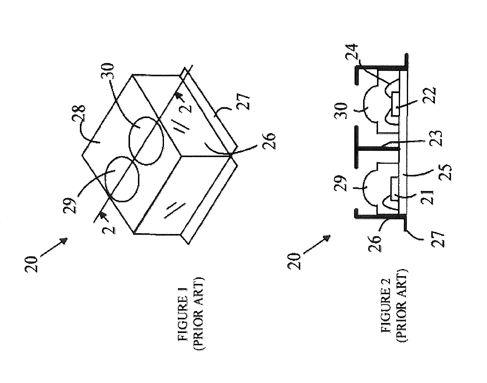
[0012]The manner in which the present invention provides its advantages can be more easily understood with reference to FIGS. 1 and 2, which illustrate a prior art transceiver module. FIG. 1 is a perspective view of transceiver 20, and FIG. 2 is a cross-sectional view of transceiver 20 through line 2-2 shown in FIG. 1. Transceiver 20 includes an LED 21 and a photodiode 22 that are bonded to a carrier 25 that includes a number of electrical traces that are utilized to connect the circuit components to the carrier and the carrier to an external printed circuit board or the like. To simplify the drawings, these traces and the control circuitry that operates the LED and photodiode have been omitted. The connections to the top surfaces of the dies containing the LED and the photodiode are made via wire bonds that connect the pads on the top surface of the dies to pads on the top surface of carrier 25. A typical wire bond is shown at 24.

[0013]After the dies have been mounted on carrier 25...


PUM


Abstract

A transceiver having a light source die, a photodetector die and a substrate is disclosed. The substrate has a first well in which the light source die is mounted and a second well in which the photodetector die is mounted. The substrate has a reflective surface which blocks light leaving the light source from reaching the photodetector unless the light is reflected by an object external to the transceiver. The reflecting surface of the second well in the substrate is shaped to concentrate light received from outside the transceiver onto the photodetector, and in one aspect of the invention it comprises a non-imaging optical element. The light source is powered by applying a potential between first and second contacts on the light source die. A signal is generated between first and second contacts on the photodetector die in response to illumination of the photodetector die.

Description

BACKGROUND OF THE INVENTION[0001]Optical transceivers are utilized in a number of systems to transmit and receive data and to implement proximity detectors. Such devices typically include a light source, which is typically a light emitting diode (LED) that is used to transmit data by modulating the intensity of the light source and a photodiode that receives the modulated light signals. Optical transceivers operating in the infrared are utilized in computers and handheld devices for transferring data from one device to another without requiring that the devices be connected together by a wire or cable. In such systems, the two devices are positioned relative to one another such that light from the transmitter in the first device is received by the optical receiver in the second device, and vice versa.[0002]In a proximity detector, the light from a transmitter in the transceiver is received by the receiver in that transceiver after the light has been reflected from the surface of an ...

Claims


Application Information

Patent Timeline
Patent Type & Authority Patents(United States)
IPC IPC(8): H01L31/12H01L31/16
CPCH04B10/40H01L2224/48091H01L2924/00014H01L2924/3025H01L2924/00
Inventor GOH, TECK CHAICHEN, DENG PENGSURESH, BASOORTAN, WEE SINNG, PENG YAMLIM, SIN HENGYEE, PAK HONG
Owner AVAGO TECH INT SALES PTE LTD
Why Eureka
Try Eureka