
Antenna

a technology of antennas and antennas, applied in the field of antennas, can solve the problems of affecting the performance of the whole wireless network application, consuming a lot of space, and affecting the performance of two or more antennas, so as to and broaden the antenna band

Active Publication Date: 2010-11-30
WISTRON NEWEB
View PDF11 Cites 158 Cited by
  • Summary
  • Abstract
  • Description
  • Claims
  • Application Information

AI Technical Summary

Benefits of technology

The present invention provides an antenna that can be used in different wireless communication standards. The antenna includes a capacitor structure made up of a grounding element, a radiating element, an interconnecting element, and a conductive element. The conductive element is positioned between the grounding element and the radiating element and has a feed for receiving a current. This structure allows the antenna to have a broad band of frequencies that it can work with, and it also prevents interference between other antennas in the same device. This design eliminates the need for multiple antennas in consumer electronic products.

Problems solved by technology

The antenna seriously affects the performance of the whole wireless network application.
However, two or more antennas consume a lot of space and interfere with each other.
The prior antenna is not compatible with different wireless communication standards.
This limits applications of prior antennas.
Thus, the prior antenna is unable to satisfy modern requirements any longer.

Method used


Image

  • Antenna
  • Antenna
  • Antenna

Examples


Embodiment Construction

[0019]The present invention provides an antenna, which employs a capacitor structure constituted by a conductive element and a radiating element to broaden the band of the antenna. Reference will now be made in detail to the present preferred embodiments of the invention, examples of which are illustrated in the accompanying drawings. Wherever possible, the same reference numbers are used in the drawings and the description to refer to the same or like parts.

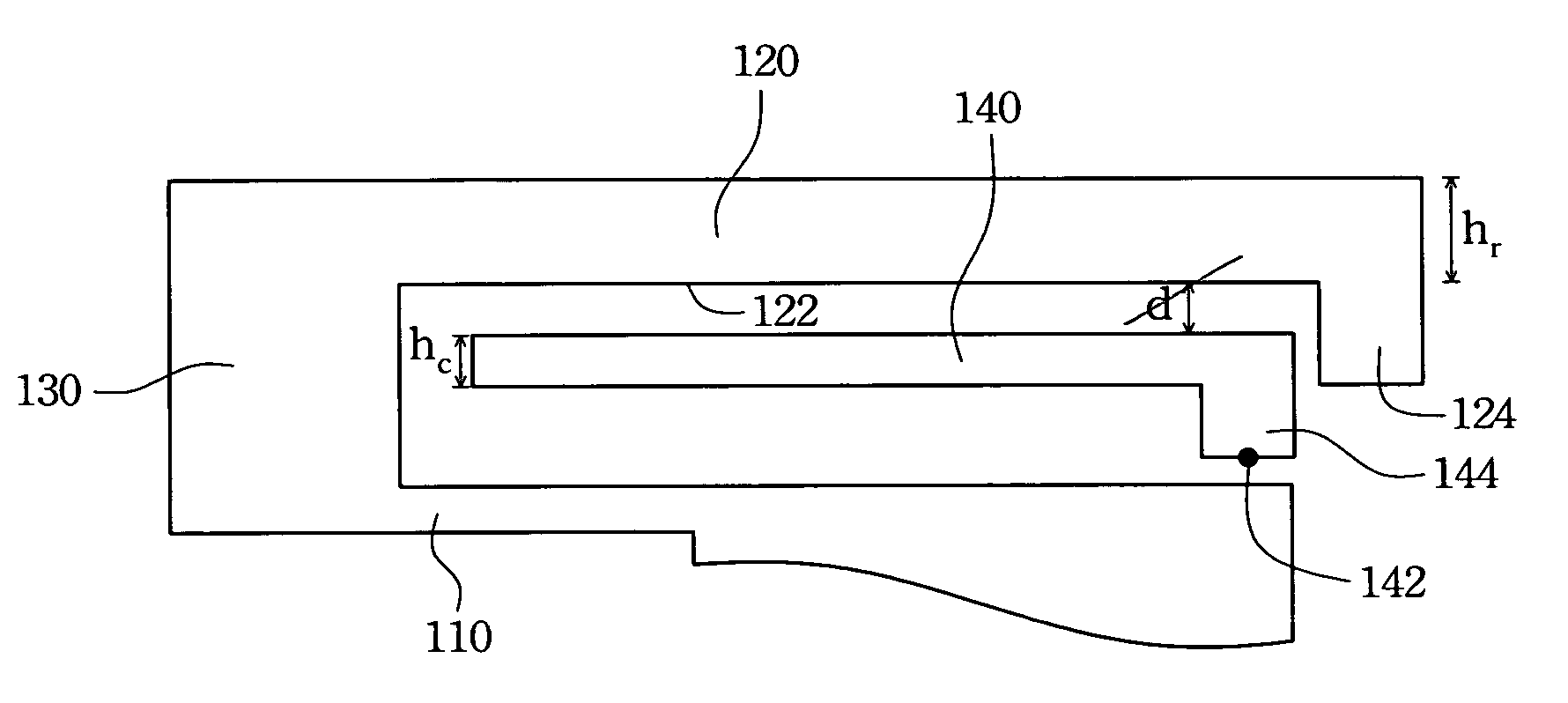
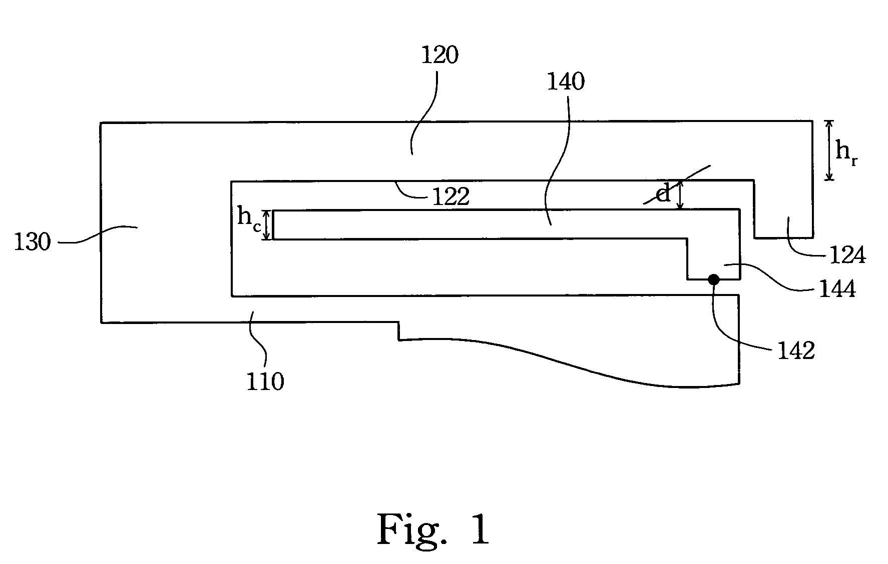
[0020]Reference is made to FIG. 1, which is a side view of an antenna according to one preferred embodiment of the invention. In FIG. 1, an antenna includes a grounding element 110, a radiating element 120, an interconnecting element 130 and a conductive element 140. The interconnecting element 130 connects the radiating element 120 and the grounding element 110. The conductive element 140 is disposed between the grounding element 110 and the radiating element 120, and the conductive element 140 is positioned apart from the grou...


PUM


Abstract

An antenna includes a grounding element, a radiating element, an interconnecting element and a conductive element. The interconnecting element connects the radiating element and the grounding element. The conductive element is disposed between the grounding element and the radiating element and apart from the grounding element and the radiating element. Moreover, the conductive element has a feed positioned thereon.

Description

RELATED APPLICATIONS[0001]The present application is based on, and claims priority from, Taiwan Application Serial Number 95117726, filed May 18, 2006, the disclosure of which is hereby incorporated by reference herein in its entirety.BACKGROUND[0002]1. Field of Invention[0003]The present invention relates to an antenna. More particularly, the present invention relates to an antenna which employs a capacitor structure to broaden the band of the antenna.[0004]2. Description of Related Art[0005]As the rapid development of wireless communication technologies, many electronic apparatus, such as mobile phones, computers or network applications, have used wireless communication technologies to communicate with each other, wireless wide area network (WWAN) especially. More and more manufacturers want to incorporate WWAN into consumer electronic products because WWAN can provide communication within a local, nationwide or even global area.[0006]A typical receiving or transmitting wireless c...

Claims


Application Information

Patent Timeline
Patent Type & Authority Patents(United States)
IPC IPC(8): H01Q1/38
CPCH01Q9/42
Inventor LIU, CHIH-KAI
Owner WISTRON NEWEB
Learn More