
Remote control receiver and electronic equipment including the same

a technology of remote control receiver and electronic equipment, applied in the direction of electromagnetic transmission, telemetry/telecontrol selection arrangement, electric devices, etc., can solve the problems of size reduction and price reduction impairmen

Active Publication Date: 2010-11-30
MICROSOFT TECH LICENSING LLC
View PDF9 Cites 2 Cited by
  • Summary
  • Abstract
  • Description
  • Claims
  • Application Information

AI Technical Summary

Benefits of technology

[0008]Accordingly, an object of the present invention is to provide a remote control receiver which makes it possible to achieve size reduction and price reduction.
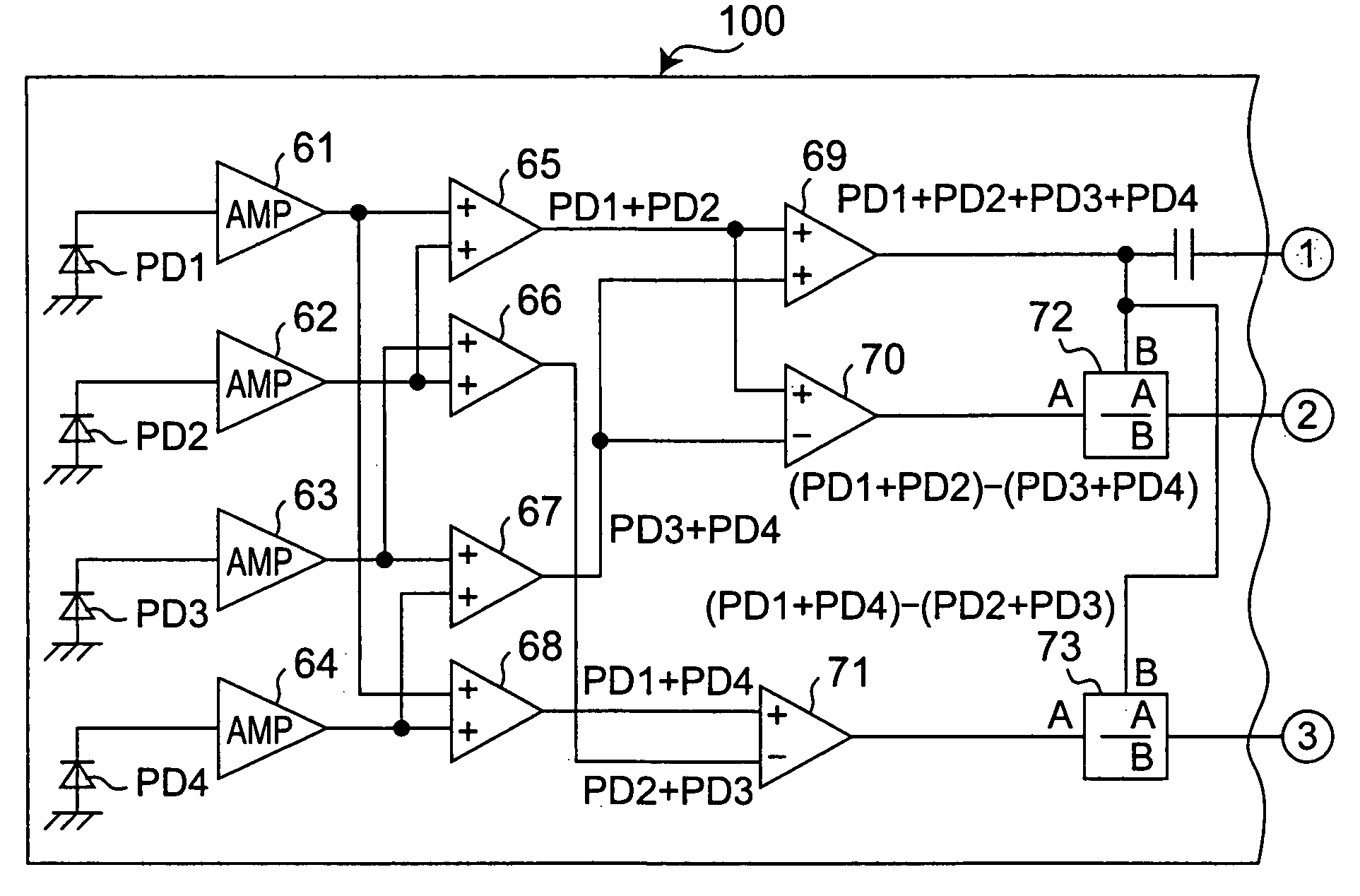
[0013]In the remote control receiver of this invention, the second signal processing circuit calculates a difference between the signals outputted by the plurality of light-receiving regions to obtain and output a directional signal representing a direction in which the incident light has been incident on the plurality of light-receiving regions. Therefore, depending on the directional signal, the direction in which the incident light has been incident with respect to the plurality of light-receiving regions is detected. Also, the first signal processing circuit adds up the signals outputted by the plurality of light-receiving regions and, based on a resulting signal, demodulates and outputs the remote control signal. Thus, the original remote control signal is obtained. In this case, since the first signal processing circuit adds up the signals outputted by the plurality of light-receiving regions, wastefulness in area of the light-receiving regions can be reduced so that the S / N ratio (signal-to-noise ratio) can be improved. Still, in this remote control receiver, since at least the plurality of light-receiving regions are housed in one common mold package, more size reduction and price reduction become achievable as compared with the prior art example.
[0016]In systems in which this type of remote control receiver is incorporated, there has been a possibility that the system may malfunction due to occurrence of a mis-recognition that an non-objective remote control signal (e.g., a remote control signal used for another system employed in the same room), when having been incident in the form of incident light, is mistaken as an objective remote control signal. In this connection, the remote control receiver of this one embodiment includes an external input terminal for turning on or off power supply to the second signal processing circuit. Therefore, for example, with the provision of an external circuit for receiving an output of the first signal processing circuit of the remote control receiver, the external circuit feeds the external input terminal a signal for turning on the power supply to the second signal processing circuit only when the first signal processing circuit outputs an objective remote control signal, while the external circuit feeds the external input terminal a signal for turning off the power supply to the second signal processing circuit when the first signal processing circuit outputs no objective remote control signal. Whether the signal is an “objective remote control signal” or not is discriminated depending on the format of the remote control signal as an example. In such a case, in this remote control receiver, even if an non-objective remote control signal has been incident in the form of incident light, the second signal processing circuit is not actuated, so that no directional signal is outputted. Therefore, even if any non-objective remote control signal has been incident in the form of incident light, the system does not malfunction. Thus, with the remote control receiver of this one embodiment, any malfunction of the system in which the remote control receiver is incorporated can be prevented.
[0023]In systems in which this type of remote control receiver is incorporated, there are some cases where only control of a uniaxial direction suffices for the control responsive to the direction in which the incident light becomes incident (i.e., a direction of the operator of the remote control transmitter). In this connection, in the remote control receiver of this one embodiment, the plurality of light-receiving regions are two light-receiving regions included in a two-element PIN photodiode, and the directional signal to be outputted by the second signal processing circuit is a signal of a uniaxial direction in which the incident light becomes incident. Therefore, the remote control receiver is suitable for a system for which only such control for a uniaxial direction suffices. That is, in the remote control receiver of this one embodiment, the separation zone (region insensitive to light) for electrically separating the light-receiving regions from each other needs only to be a smaller one. As a result, wastefulness in area of the surface of the semiconductor chip that include the two-element PIN photodiode can be reduced, allowing the S / N ratio (signal-to-noise ratio) to be most advantageous.
[0029]In the remote control receiver of this invention, since the PSD and the first and second signal processing circuits are housed in one common mold package, size reduction and price reduction become achievable.

Problems solved by technology

However, in the remote control receivers described above, in which the individual photodiodes are assembled in independent mold packages, respectively, there is a problem that size reduction and price reduction are impaired.

Method used


Image

  • Remote control receiver and electronic equipment including the same
  • Remote control receiver and electronic equipment including the same
  • Remote control receiver and electronic equipment including the same

Examples


Embodiment Construction

[0066]Hereinbelow, the present invention will be described in detail by way of embodiments thereof illustrated in the accompanying drawings.

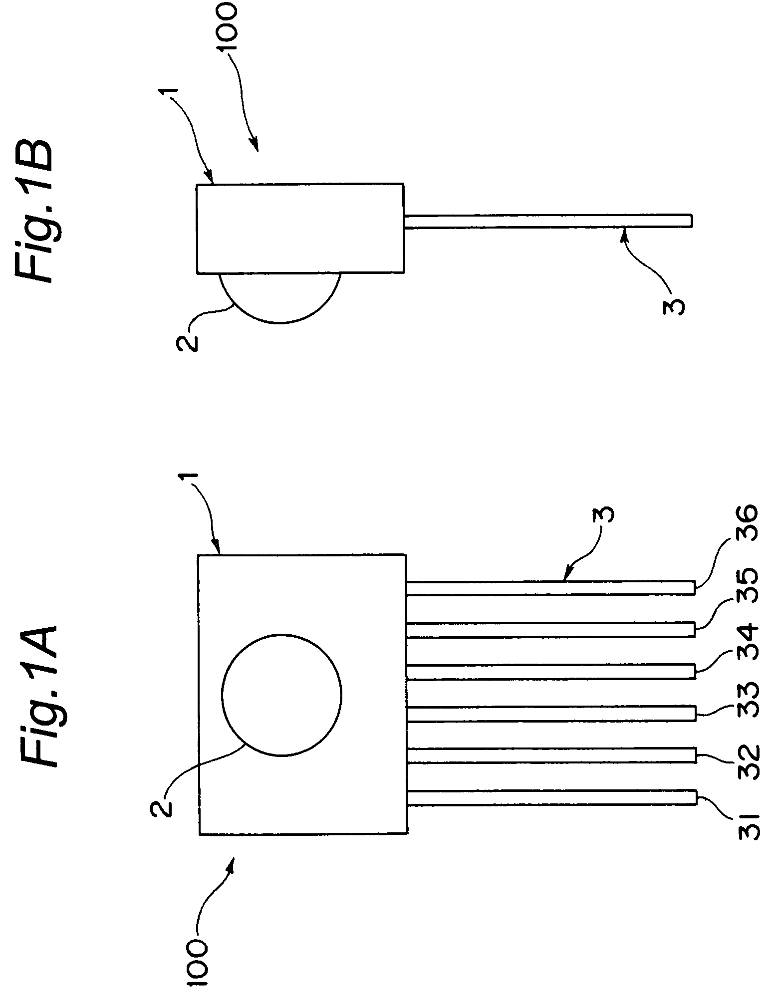
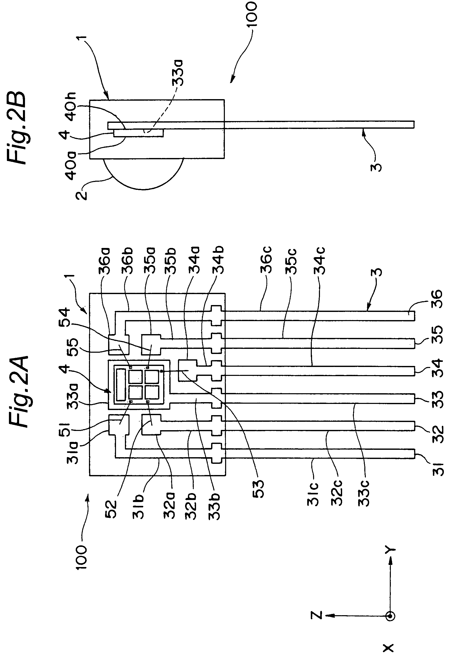
[0067]FIG. 1A shows an appearance of a remote control receiver which is an embodiment of the invention and which is suitably incorporated into a TV (television) set. FIG. 1B shows the remote control receiver of FIG. 1A, as viewed from the right side. FIGS. 2A and 2B are views corresponding to FIGS. 1A and 1B, respectively, with a mold package 1 imaginarily depicted as transparent.

[0068]As well apparent from FIG. 2A, this remote control receiver has lead frames 31, 32, 33, 34, 35, 36 (which are generically represented by reference numeral 3). The lead frames 31, 32, 33, 34, 35, 36 include rectangular-shaped land portions 31a, 32a, 33a, 34a, 35a, 36a for wire bond or die bond, inner lead portions 31b, 32b, 33b, 34b, 35b, 36b, and outer lead portions 31c, 32c, 33c, 34c, 35c, 36c, respectively. A rectangular parallelopiped-shaped semiconductor chip ...


PUM


Abstract

At least a plurality of light-receiving regions for receiving remote control signals, respectively, in a form of incident light and performing photoelectric conversion of the signals are provided in one common mold package. The remote control receiver includes a first signal processing circuit for adding up signals outputted by the plurality of light-receiving regions and, based on a resulting signal, demodulating and outputting the remote control signal. The remote control receiver also includes a second signal processing circuit for calculating a difference between the signals outputted by the plurality of light-receiving regions to obtain and output a directional signal representing a direction in which the incident light has been incident on the plurality of light-receiving regions.

Description

CROSS-REFERENCE TO RELATED APPLICATIONS[0001]This Nonprovisional application claims priority under 35 U.S.C. §119(a) on Patent Application No. 2006-227739 filed in Japan on Aug. 24, 2006, the entire contents of which are hereby incorporated by reference.BACKGROUND OF THE INVENTION[0002]The present invention relates to remote control receivers and, more particularly, to a remote control receiver capable of detecting a direction in which an operator of a remote control transmitter is present.[0003]The invention also relates to an electronic equipment including such a remote control receiver.[0004]As this type of remote control receiver, a conventionally known one is shown in FIG. 13A, in which a plurality of photodiodes 402A, 402B, 402C, 402D, 402E are provided on one PCB (Printed Circuit Board) 401 so as to be positioned in directions different from one another so that an incoming direction of light (i.e., a direction of an operator of the remote control transmitter) is detected base...

Claims


Application Information

Patent Timeline
Patent Type & Authority Patents(United States)
IPC IPC(8): H04B10/06H04B10/10H04Q9/00
CPCH04B10/1141
Inventor ISHIHARA, TAKEHISAWADA, HIDEO
Owner MICROSOFT TECH LICENSING LLC
Learn More