Power transmission network

a power transmission network and wireless technology, applied in power management, optical radiation measurement, instruments, etc., can solve the problems of not being practical in all applications, not always possible or practical to hardwire or plug in every device, and each motion sensor requires power, so as to achieve the effect of a battery insid

Active Publication Date: 2010-11-30
POWERCAST
View PDF16 Cites 506 Cited by
  • Summary
  • Abstract
  • Description
  • Claims
  • Application Information

AI Technical Summary

Benefits of technology

[0008]The present invention eliminates the need for a hardwired connection for each sensor or device. The power for the device is derived from a wireless power network. This power can be used to directly power the device or to recharge or augment an internal battery. With the present invention, the device becomes wireless in both a communication and powering sense.

Problems solved by technology

It is not always possible or practical to hardwire or plug-in every device.
The problem with this solution is that each motion sensor requires power.
This may not be practical in all applications.

Method used


Image

  • Power transmission network
  • Power transmission network
  • Power transmission network

Examples


Embodiment Construction

[0035]A complete understanding of the invention will be obtained from the following description when taken in connection with the accompanying drawing figures wherein like reference characters identify like parts throughout.

[0036]For purposes of the description hereinafter, the terms “upper”, “lower”, “right”, “left”, “vertical”, “horizontal”, “top”, “bottom”, and derivatives thereof shall relate to the invention as it is oriented in the drawing figures. However, it is to be understood that the invention may assume various alternative variations and step sequences, except where expressly specified to the contrary. It is also to be understood that the specific devices and processes illustrated in the attached drawings, and described in the following specification, are simply exemplary embodiments of the invention. Hence, specific dimensions and other physical characteristics related to the embodiments disclosed herein are not to be considered as limiting.

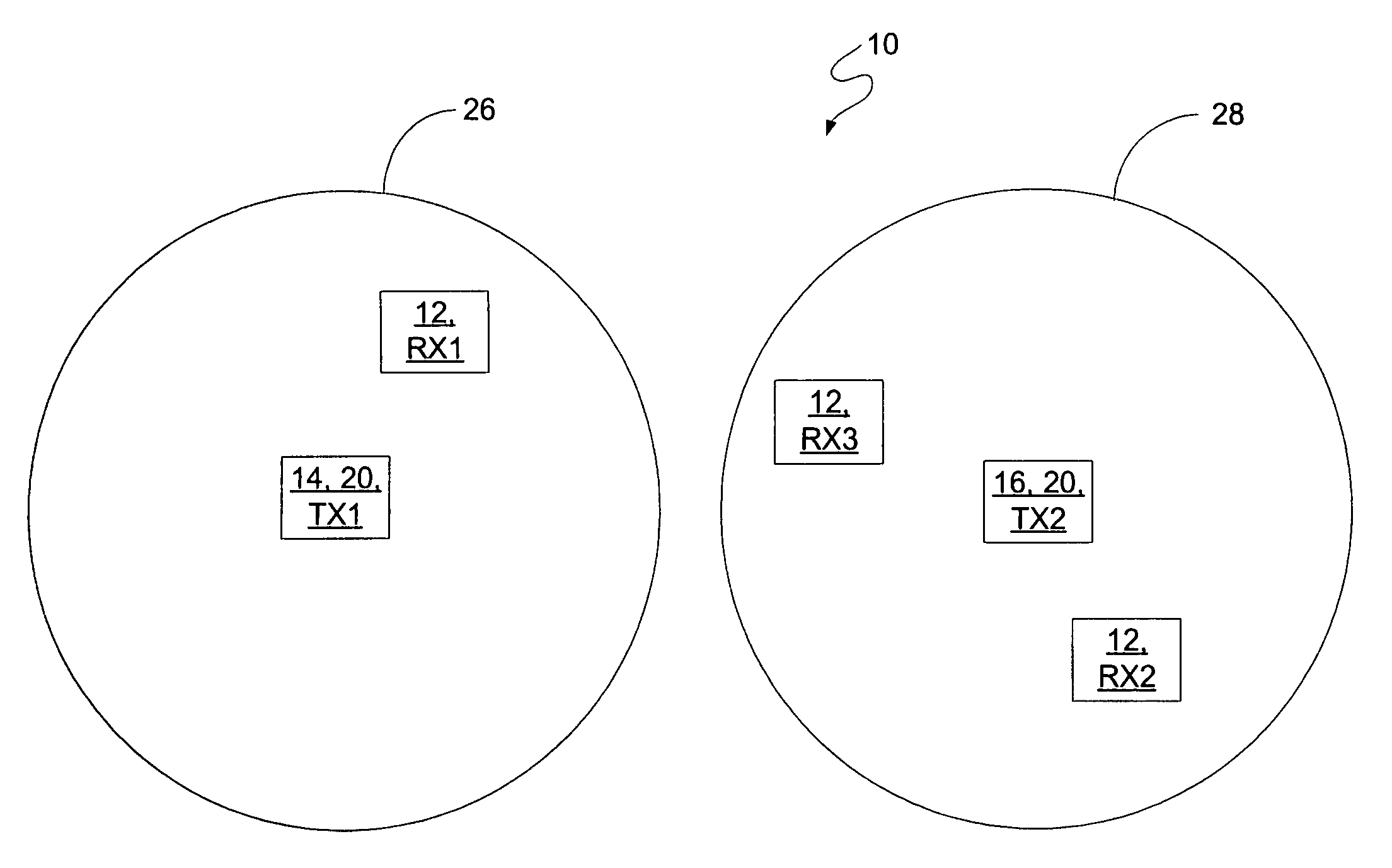
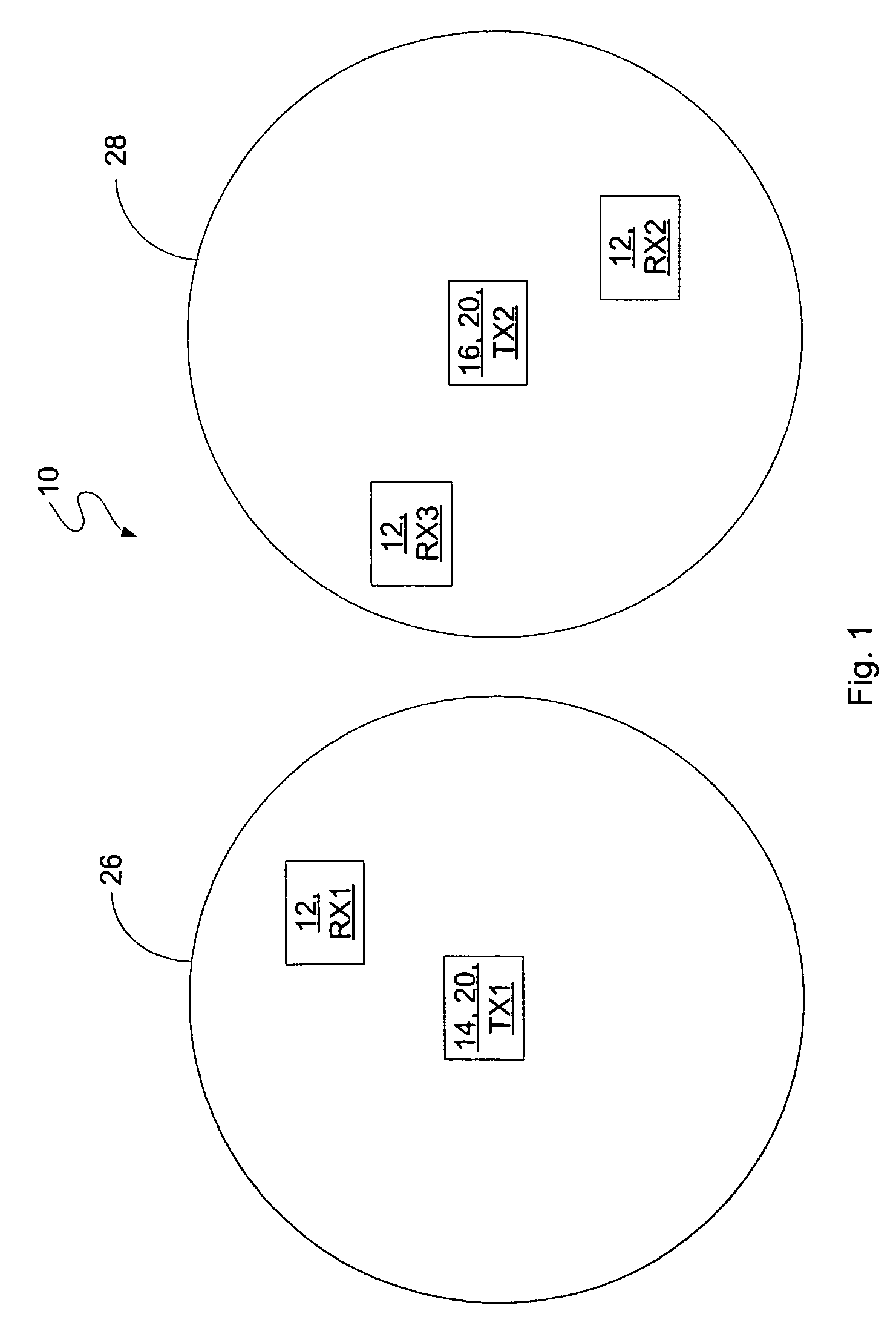
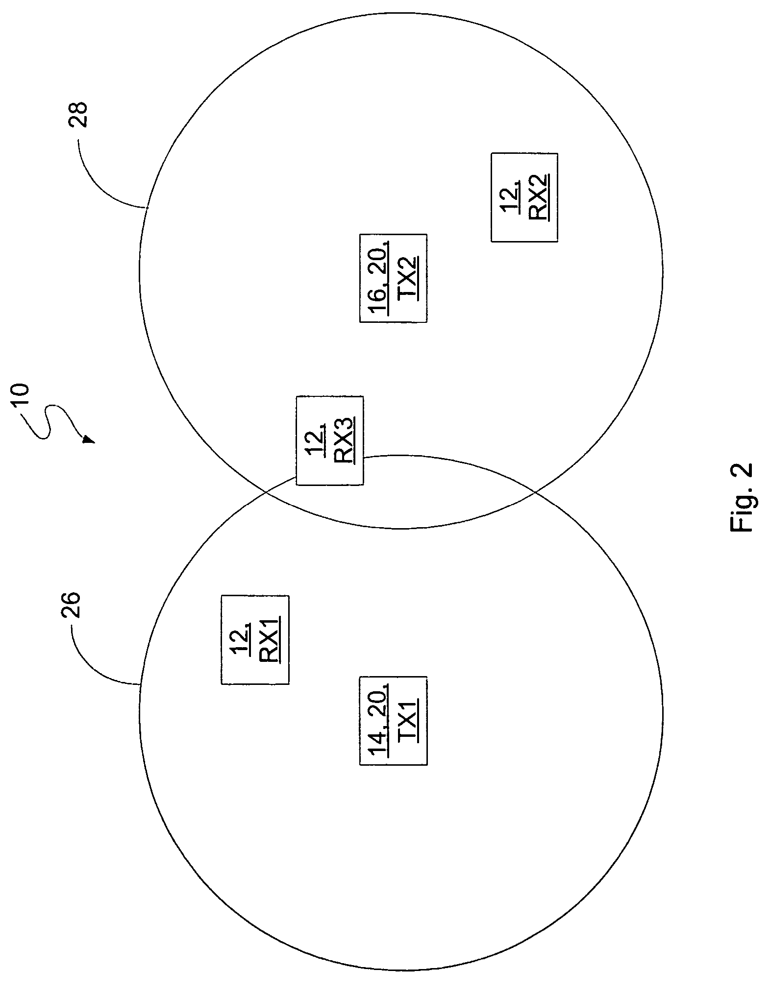
[0037]Referring to the drawin...


PUM


Abstract

A network for power transmission to a receiver that converts the power into current includes a first node for transmitting power wirelessly in a first area. The first area has a minimum electric or magnetic field strength. The network includes a second node for transmitting power wirelessly in a second area. The second area has a minimum electric or magnetic field strength and overlaps the first area to define an overlap area. In another embodiment, the network includes a source in communication with the first and second nodes which provides power to them. Also disclosed are methods for power transmission to a receiver that converts the power into current.

Description

CROSS-REFERENCE TO RELATED APPLICATIONS[0001]This application claims priority to U.S. Provisional Patent Application No. 60 / 683,991, filed May 24, 2005, and entitled “Power Transmission Network.”FIELD OF THE INVENTION[0002]The present invention is related to wireless power transmission networks. More specifically, the present invention is related to wireless power transmission networks having overlapping areas and / or having a plurality of nodes.BACKGROUND OF THE INVENTION[0003]Power transmission networks are around us every day. The most common is the alternating current (AC) power network within our homes and office buildings. The utility companies use this wired network to supply AC power to us. This network is capable of supplying large amounts of power to a device directly connected to it.[0004]The key to the operation of this network is the direct connection. It is not always possible or practical to hardwire or plug-in every device. An example of this can be seen by examining ...

Claims


Application Information

Patent Timeline
Patent Type & Authority Patents(United States)
IPC IPC(8): H04B1/38H04W52/34
CPCH02J17/00H04B7/10H04W52/34H02J50/20H02J50/80H02J50/402H04W52/04
Inventor SHEARER, JOHN G.GREENE, CHARLES E.HARRIST, DANIEL W.
Owner POWERCAST
Why Eureka
Try Eureka