Optical neural network

a neural network and optical technology, applied in the field of optical neural networks, can solve problems such as difficulty in flexibly changing the connection weight, and achieve the effect of flexible change of the connection weigh

Inactive Publication Date: 2010-12-07
HIROSHIMA UNIVERSITY
View PDF8 Cites 30 Cited by
  • Summary
  • Abstract
  • Description
  • Claims
  • Application Information

AI Technical Summary

Benefits of technology

[0009]Accordingly, the present invention was made in order to solve the problem, and it is an object of the present invention to provide an optical neural network that allows the flexible change of the connection weight.

Problems solved by technology

Therefore, there is a problem that it is difficult to change the connection weight flexibly.

Method used


Image

  • Optical neural network
  • Optical neural network
  • Optical neural network

Examples


Embodiment Construction

[0052]With reference to drawings, embodiments of the present invention will be described in detail. In the drawings, the same or similar components are denoted by the same reference numerals, and a detailed description thereof will be not repeated.

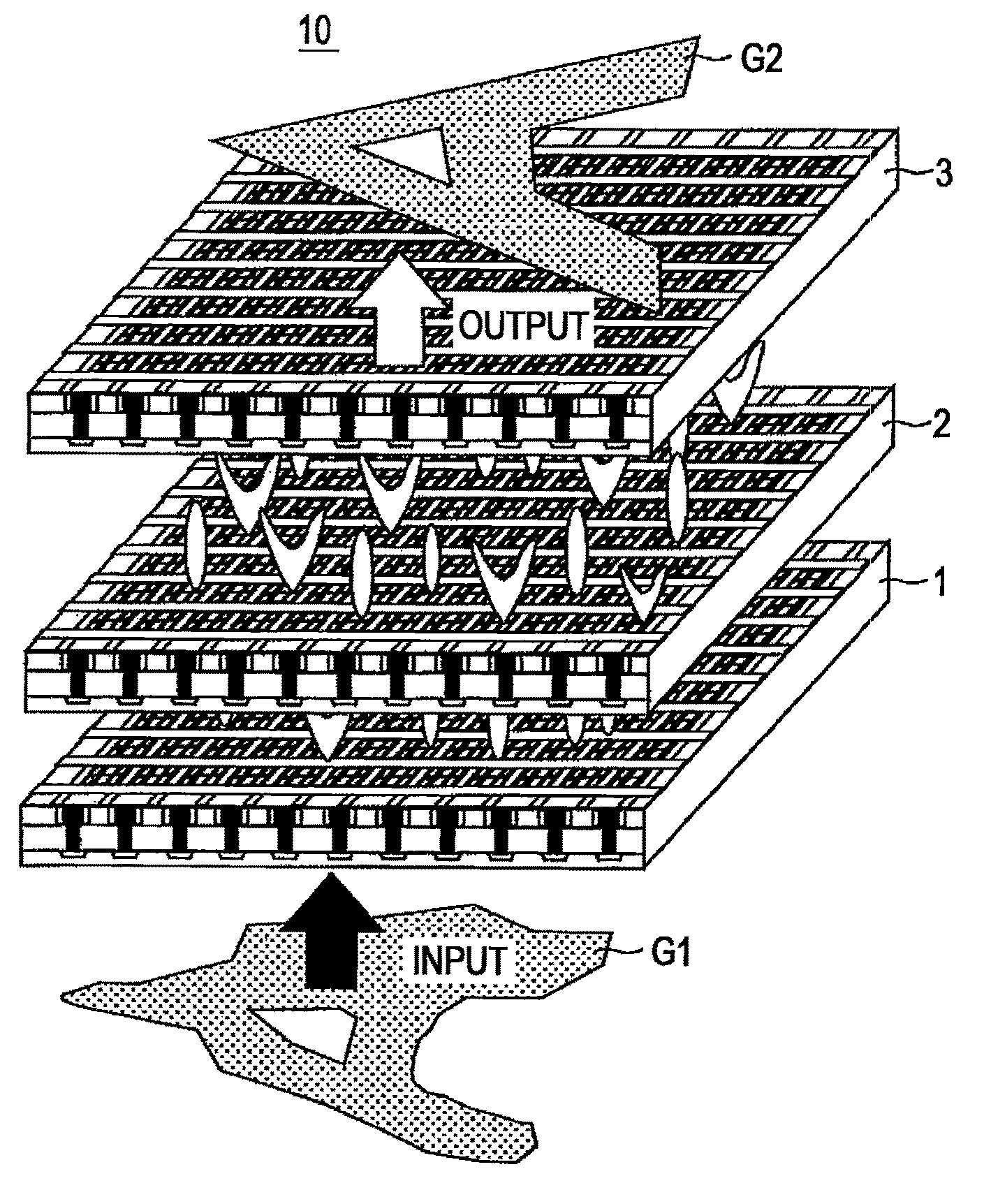
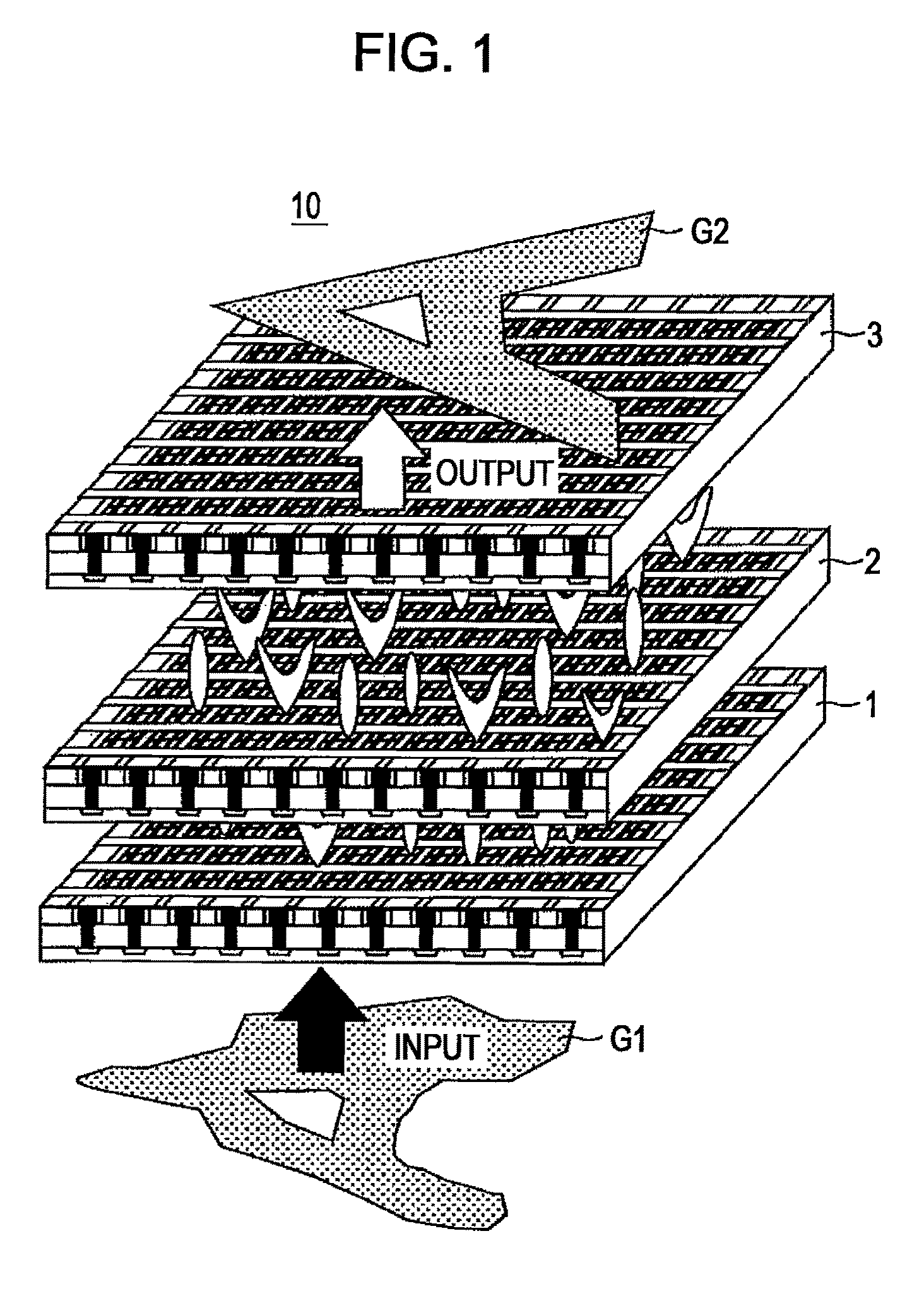
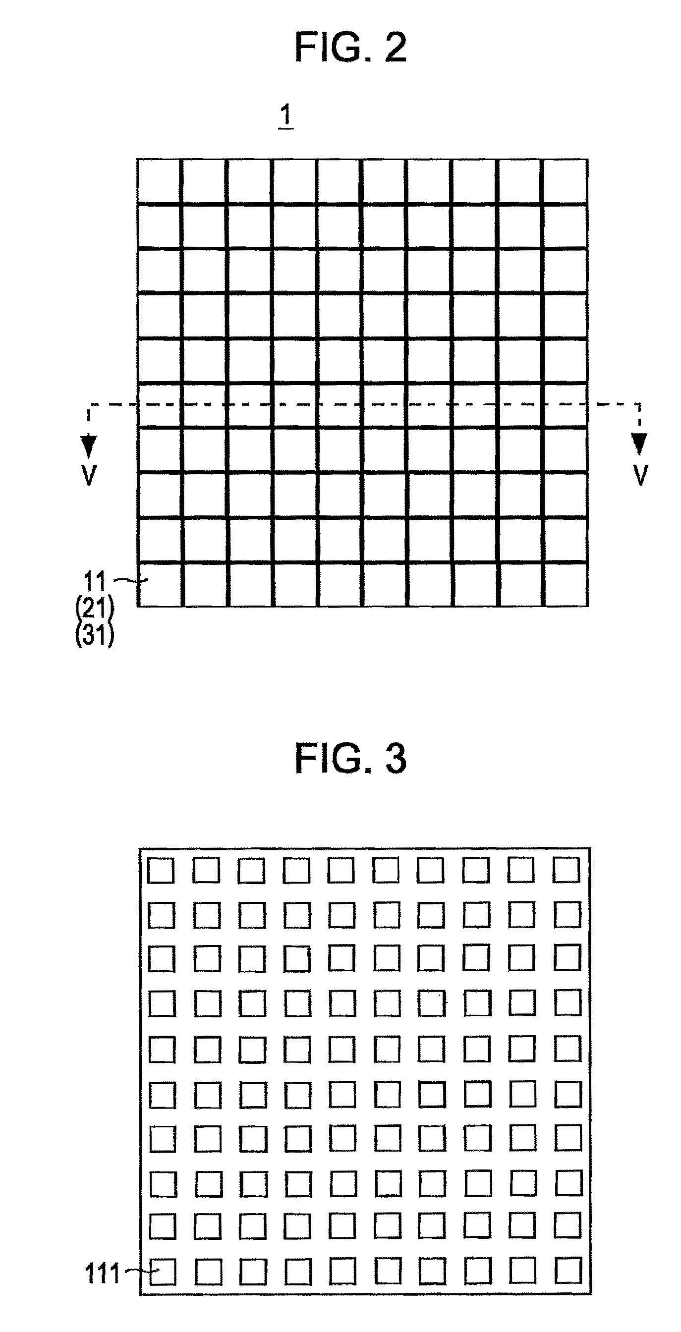
[0053]FIG. 1 is a configuration diagram of an optical neural network according to embodiment of the present invention. Referring to FIG. 1, an optical neural network 10 according to embodiment of the present invention includes an input layer 1, a middle layer 2 and an output layer 3.

[0054]Each of the input layer 1, the middle layer 2 and the output layer 3 is composed of a semiconductor layer. The middle layer 2 is placed to face the input layer 1, the output layer 3 is placed to face the middle layer 2.

[0055]The input layer 1 receives an input signal composed of an optical signal and outputs light having an emission angle distribution according to the signal level of the received input signal as an output signal to the middle layer 2.

[005...


PUM


Abstract

An input layer outputs light having a relatively narrow emission angle distribution to a middle layer as an output signal if the signal level of input signal is relatively high and outputs light having a relatively broad emission angle distribution to the middle layer as the output signal if the signal level of input signal is relatively low. The middle layer outputs light having a relatively narrow emission angle distribution as an output signal to an output layer if the signal level of the output signal from input layer is relatively high and outputs light having a relatively broad emission angle distribution to the output layer as an output signal if the signal level of the output signal from the input layer is relatively low.

Description

CROSS-REFERENCE TO RELATED PATENT APPLICATIONS[0001]The present application claims priority as a national stage application of the International Application No. PCT / JP2008 / 001139 filed on May 2, 2008, the entire contents of which are incorporate herein by reference in their entireties.Technical Field[0002]The present invention relates to an optical neural network.Background Art[0003]Hitherto, a neural network that performs input / output by electromagnetic waves such as light has been known (Japanese Unexamined Patent Application Publication No. 7-129533). The neural network includes an input layer, a middle layer and an output layer. Each layer of the input layer, the middle layer and the output layer includes a plurality of neurons. Each of the plurality of neurons is composed of a light receiving unit and a light emitting unit.[0004]An input signal is input to the input layer by using a plurality of wavelength bands. In each neuron in the input layer, the light receiving unit ident...

Claims


Application Information

Patent Timeline
Patent Type & Authority Patents(United States)
IPC IPC(8): G06F15/18G06E3/00
CPCG06N3/067H01L27/15H01S5/0425H01S5/183H01S5/423H01S2301/18H01S5/04252G06N3/0675
Inventor YOKOYAMA, SHIN
Owner HIROSHIMA UNIVERSITY
Why Eureka
Try Eureka